Proto Pedal Example: Analog Equalizer Project
 Byron J.
Testing
Preparation
We'll start testing with a handful of sanity checks, or the proverbial "smoke test".
- Start by connecting power, either a 9V battery, or an external supply.
- Then connect a TS jack to the input. Recall that the input jack also serves as a hidden power switch, which is required to get the circuit to power up.
- Quickly and carefully feel the ICs and MOSFET. They should be cool to the touch. If not, power down and doublecheck your work.
- If they're getting warm, doublecheck that the ICs are oriented correctly, and that there aren't any solder bridges between adjacent fillets.
- Press the stomp switch a couple of times. The LED should toggle on and off with each actuation. The circuit is active when the LED is on, and bypassed when the LED is off.
- If you're using a bench supply with a built in ammeter, check that the current draw isn't excessive. On our bench, the device drew miniscule current when bypassed, and about 7 mA when switched to active.
Knowing the Controls
Since they're just flying on the ends of the wiring harness, it can be hard to tell which potentiometer is which. The pot with the yellow wire is the low frequency control, and the pot with the green wire is the high frequency control.
Before moving on to the next step, make sure that the pedal is active, the LED is on, and set both pots to the center of their rotation.
Operational Testing
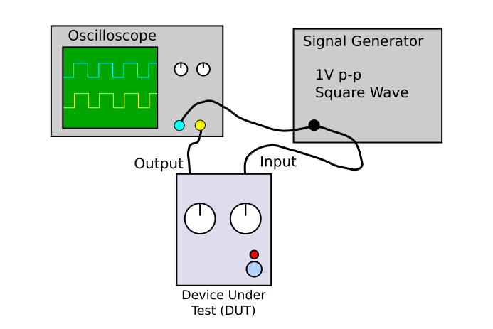
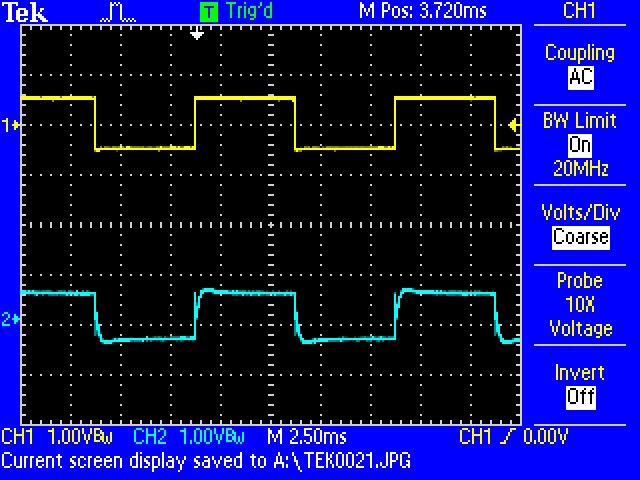
If you've got a function generator and oscilloscope, you can quickly test an EQ using a low frequency square wave.
Connect the signal generator to the input, and set it for 100 Hz at 1 Vpeak-to-peak. You can view the output by connecting to the output tip test point, adjacent to the output jack. We'll be using a two-channel oscilloscope, with the first channel, in yellow, observing the signal generator output and the second channel, in blue, scoping the output of the EQ.
With both controls centered, the output will be very close to in input.
We'll first check the low frequencies. As you rotate the knob, the plateaus of the square wave will bend. Rotating the control colckwise increases the low frequency content, and the plateaus bend outward.
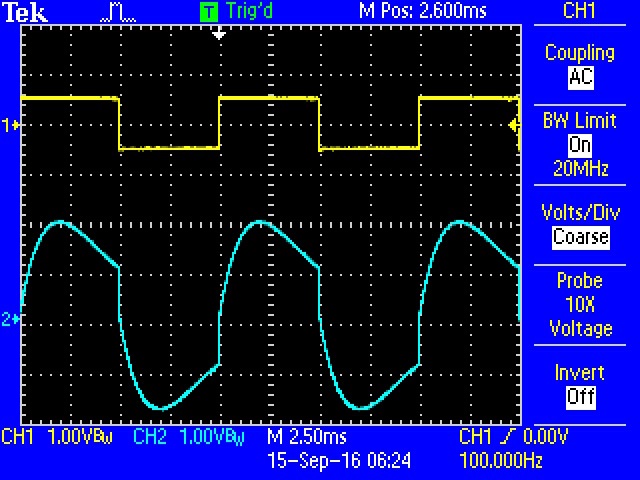
Rotating the control counter-clockwise bends the plateaus inward.
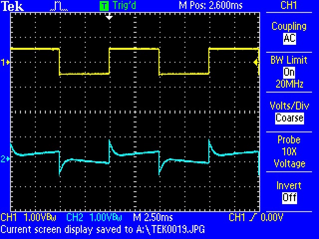
As you adjust the high frequencies, it becomes apparent just past the rising and falling edges of the square. When the high frequencies are rotated clockwise, the boost causes the edges to ring and overshoot.
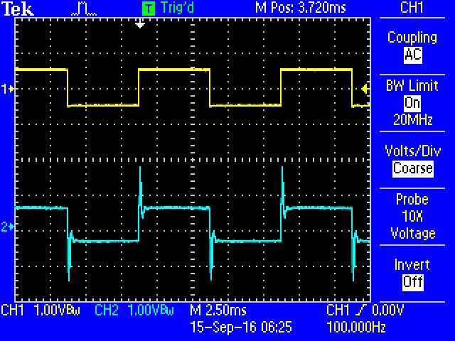
A cut causes a rounded second edge to appear near the vertical segments.
Failsafe
If you don't have a signal generator and oscilloscope availabile, there's no harm in just plugging the pedal in and listening to it. It's wise to perform the smoke test listed above first, and keep the master volume low until you're confident that the EQ is well behaved.
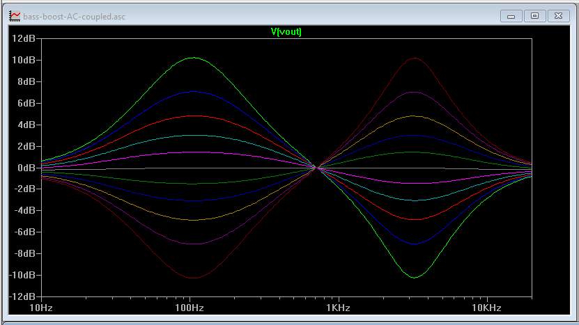
Performance
The frequency response is illustrated below, showing the effect of turning the potentiometers from their lowest to highest settings.
Seal It Up
If your testing yields satisfactory results, you're done!

You can put the pots through the enclosure, stick on knobs, and deploy the pedal for use!
In Use
This circuit performs best when the input signal isn't too hot. It's OK with a 1 Vpeak-to-peak input, but much above that and it distorts a bit (part of our testing involved a bass guitar with a high-output pickup that could easily produce 4 Vpp!). If you don't like the distortion, there are several potential fixes, listed below in order of increasing required effort.
- Turn down the volume a bit.
- Swap out the LM358 op-amps for better ones. We had success with NE5532's, at the cost of much higher quiescent current consumption.
- Increase the power supply voltage. Some pedal supplies offer an 18V output, or you can use two 9V batteries in series.
- Dig deeper into the design to add an attenuator on the input, with makeup gain on the output.