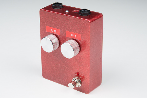
Proto Pedal Example: Analog Equalizer Project
Resources and Going Further
Resources
- The basis for this project was Fred Forssell's Equalizer design.
- The basis for the design is explored in his EQ whitepaper
- There is a secondary document that contains detailed information on the gyrator math.
- The National Semiconductor Audio Radio Handbook contains a similar gyrator EQ circuit. The gyrators are slightly different, and their explanation is much more math-heavy.
- If you're really interested in EQ circuits, Douglas Self's Small Signal Audio Design is a great reference.
Going Further
Modifications
The filters in the circuit are highly configurable. By adjusting the component values, the center frequencies can be moved, bandwidths adjusted, and the maximum amount cut and boost altered. The gyrator paper mentioned above covers the basics.
For bass guitar, simply doubling the values of the gyrator capacitors (C4, C5, C6, C7, C8 and C9) will drop the bands by an octave.
If you'd like to simulate different component values, there is an LT SPICE simulation in the Github repository.
Try other capacitor chemistries, too. Again, the design challenge was to design something using only parts in stock at SparkFun. If you've got a stash of fancier caps, this is a great circuit to try them in. Polyester film (Mylar) caps work nicely in audio circuits, and silver-mica caps are also highly regarded.
As mentioned in the testing section, the LM358 op-amps have been surpassed by newer ones. They share a footprint with many other dual op-amps.
Finallly, if you're really ambitious, and can add more frequency bands by duplicating the potentiometer-gyrator stages. The heart of this circuit is the basis for a multi-band graphic equalizer.
