Pro Micro & Fio V3 Hookup Guide
 jimblom
Hardware Overview: Pro Micro
Before we get into installing and using the Pro Micro, let's quickly look at the board -- examine its inputs, outputs, and other hardware quirks.
The Pinout
All of the Pro Micro's I/O and power pins are broken out to two, parallel headers. Some pins are for power input or output, other pins are dedicated I/O pins. Further, the I/O pins can have special abilities, like analog input. Here's a map of which pin is where, and what special hardware functions it may have:
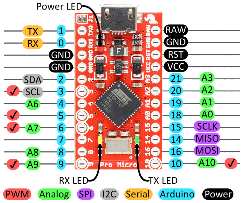
Delving a little further into which pins do what...
Power Pins
There are a variety of power and power-related nets broken out:
- RAW is the unregulated voltage input for the Pro Micro. If the board is powered via USB, the voltage at this pin will be about 4.8V (USB's 5V minus a schottkey diode drop). On the other hand, if the board is powered externally, through this pin, the applied voltage can be up to 12V.
- VCC is the voltage supplied to the on-board ATmega32U4. This voltage will depend on whether you're using a 3.3V/8MHz Pro Micro or a 5V/16MHz version, it'll be either 3.3V or 5V respectively. This voltage is regulated by the voltage applied to the RAW pin. If the board is powered through the 'RAW' pin (or USB), this pin can be used as an output to supply other devices.
- RST can be used to restart the Pro Micro. This pin is pulled high by a 10k&Ohm; resistor on the board, and is active-low, so it must be connected to ground to initiate a reset. The Pro Micro will remain "off" until the reset line is pulled back to high.
- GND, of course, is the common, ground voltage (0V reference) for the system.
I/O Pins
The Pro Micro's I/O pins -- 18 in all -- are multi-talented. Every pin can be used as a digital input or output, for blinking LEDs or reading button presses. These pins are referenced in the Arduino IDE via an integer value between 0 and 21. (The A0-A3 pins can be referenced digitally using either their analog or digital pin number).
Nine pins feature analog to digital converters (ADCs) and can be used as analog inputs. These are useful for reading potentiometers or other analog devices using the analogRead([pin]) function.
There are five pins with pulse width modulation (PWM) functionality, which allows for a form of analog output using the analogWrite([pin], [value]) function. These pins are indicated on-board with a faint, white circle around them.
There are hardware UART (serial), I2C, and SPI pins available as well. These can be used to interface with digital devices like serial LCDs, XBees, IMUs, and other serial sensors.
The Pro Micro has five external interrupts, which allow you to instantly trigger a function when a pin goes either high or low (or both). If you attach an interrupt to an interrupt-enabled pin, you'll need to know the specific interrupt that pin triggers: pin 3 maps to interrupt 0 (INT0), pin 2 is interrupt 1 (INT1), pin 0 is interrupt 2 (INT2), pin 1 is interrupt 3 (INT3), and pin 7 is interrupt 4 (INT6).
On-Board LEDs
There are three LEDs on the Pro Micro. One red LED indicates whether power is present.
The other two LEDs help indicate when data is transferring over USB. A yellow LED represents USB data coming into (RX) the the Pro Micro, and a green LED indicates USB data going out (TX).
3.3V or 5V? 8MHz or 16MHz?
Pro Micros come in two flavors, which vary by system voltage and operating frequency. The standard 5V Pro Micro runs at 16MHz, and is very comparable to an Arduino Leonardo, while the 3.3V version of the Pro Micro runs at half the speed (to remain in the safe operating zone at the lower voltage) -- 8MHz.
The operating voltage of your Pro Micro determines the maximum allowable voltage on any of the I/O pins. For example, if you have a 3.3V Pro Micro, don't interface it with something that outputs 5V.
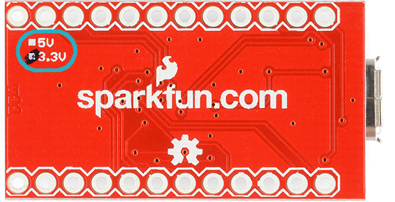
Don't forget which version you have! We'll need to differentiate between the two when we get to uploading code in Arduino. If you're not sure which version you have, check the back corner of the board. One of two boxes should be checked to indicate the operating voltage.
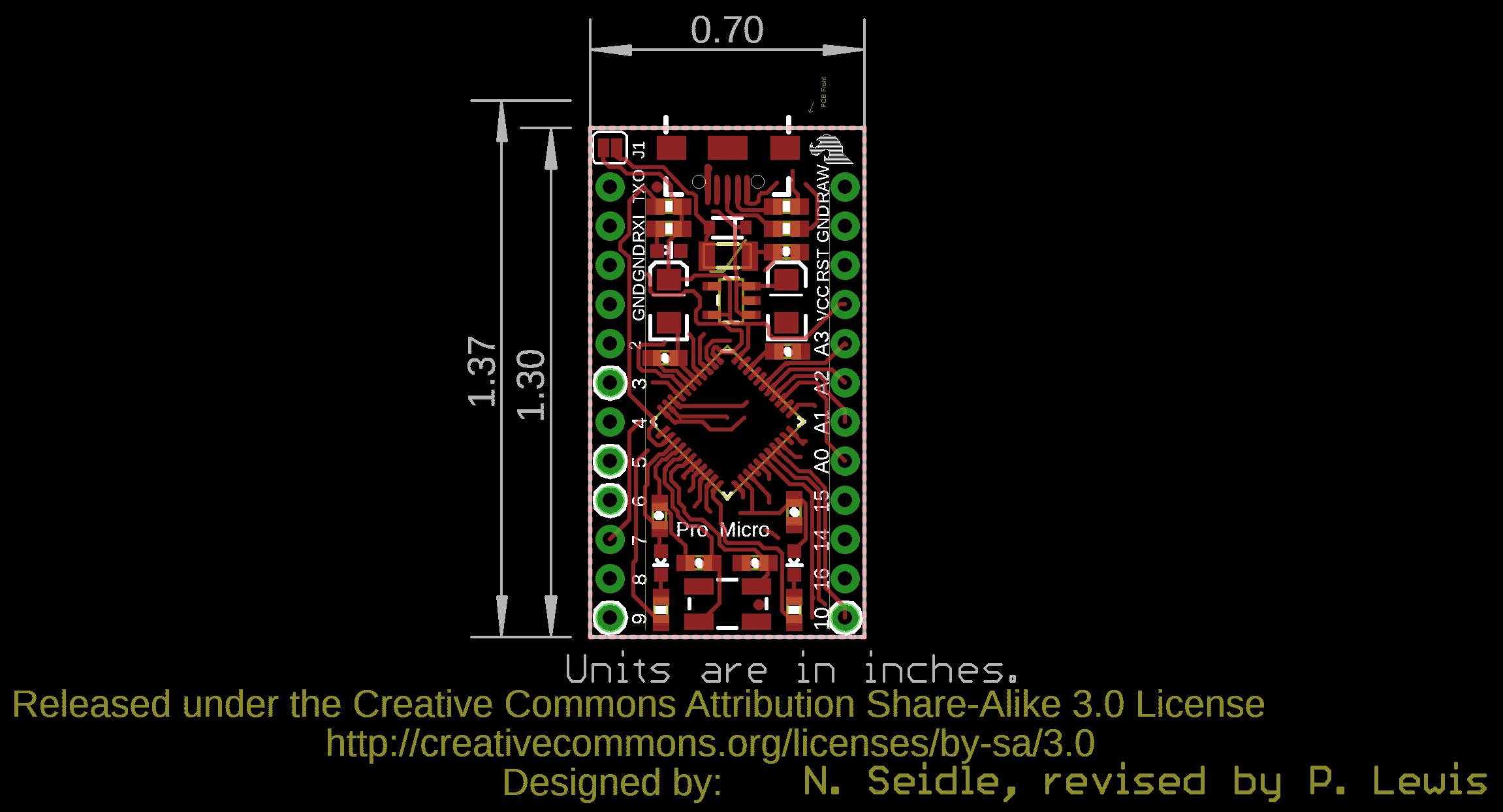
Board Dimensions
The Pro Micro is 1.30"x0.70". Note that the USB connector adds a small bit of length to the board so the total length is about 1.37".
How to Power the Pro Micro
As the Pro Micro's main feature is its innate USB functionality, the most common way to power it is via USB. In this setup, a 5V Pro Micro will be powered directly from the USB bus and a 3.3V Pro Micro will regulate the 5V supply coming in from USB down. The other end of the USB cable can be connected to either a computer, USB hub, or a USB wall adapter, which can (in most cases) provide more power.
Alternatively, if your Pro Micro is living out in the wild, out of reach of USB cables, it can be powered through either the 'RAW' or 'VCC' pins. A supply going into the 'RAW' pin will be regulated down to the correct operating voltage (5V or 3.3V). To be safe, it shouldn't be any higher than 12V, and it should be at least 1V more than the Pro Micro's operating voltage (e.g. >6V for a 5V Pro Micro).
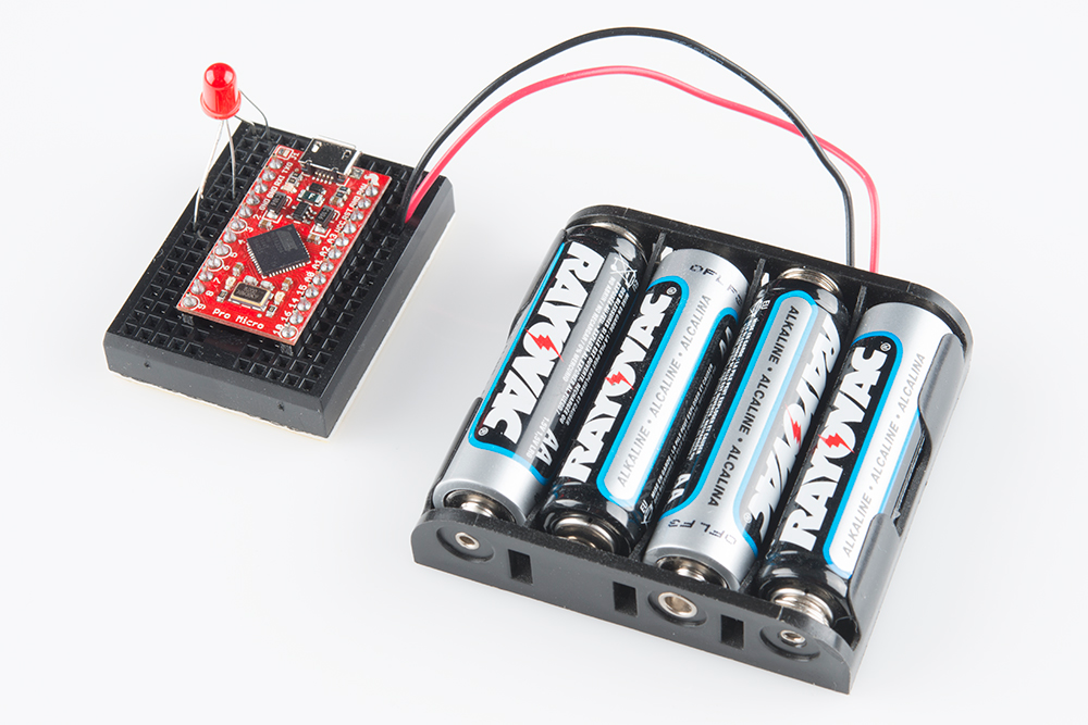
If you power the Pro Micro through the 'VCC' pin, keep in mind that this signal is unregulated. Only use this if you have a clean, regulated 3.3V or 5V supply to connect to it.
How, exactly, you power your project is up to you and the demands of your project. If you're making something battery powered, you may want to opt for the 3.3V Pro Micro, which could be powered by a LiPo battery or a couple alkalines. Make sure to check out the following tutorials for more information.