Pro Micro & Fio V3 Hookup Guide
 jimblom
Hardware Overview: Fio v3
On this page we'll examine the hardware half of the Fio v3, looking at the pinout, layout, and schematic of the board.
The Fio v3 is like an elongated Pro Micro. On one end, it's shape and pinouts are similar to it's ATmega32U4 sibling. The other end of the Fio v3 is what makes it unique: a footprint for an XBee on the bottom, and a LiPo charging circuit on the top.
The Pinout
All of the Fio v3's pins are broken out to either side of the board. Some pins are for power input or output, other pins are dedicated I/O pins. Further, the I/O pins can have special abilities, like analog input, or serial input/output. Here’s a map of which pin is where, and what special capabilities it may have:
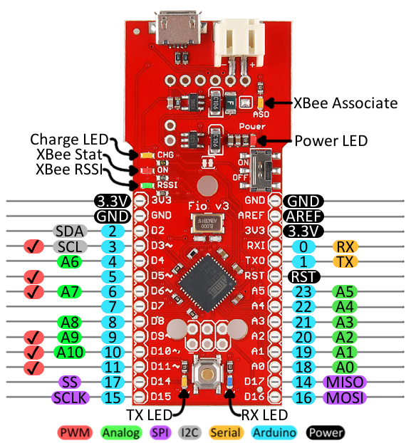
Power Pins
The pins labeled '3.3V' break out the operating voltage source of the ATmega32U4. As long as the board is powered through the white JST connector or USB, this voltage is regulated down to 3.3V. These pins can be used as outputs to supply 3.3V to other devices.
The 'RST' pin can be used to restart the Fio. This pin is pulled high by a 10kΩ resistor on the board, and is active-low, so it must be connected to ground to initiate a reset. The Fio will remain off until the reset line is pulled back to high.
I/O Pins
Many of the Fio's I/O pins are multi-talented. Every pin can be used as a digital input or output, for blinking LEDs or reading button presses. These pins are referenced in the Arduino IDE via an integer value between 0 and 23. (The A0-A10 pins can be referenced digitally via either their analog pin number or digital pin number).
Eleven pins feature analog to digital converters (ADCs) and can be used as analog inputs. These are useful for reading potentiometers or other analog devices using the analogRead([pin]) function.
There are six pins with pulse width modulation (PWM) functionality, which allows for a form of analog output using the analogWrite([pin], [value]) function. These pins are indicated on-board with a faint white circle around the pin.
There are also hardware UART (serial), I2C, and SPI pins available. These can be used to interface with digital devices like serial LCDs, IMUs, and other serial sensors.
The Fio v3 has five external interrupts, which allow you to instantly trigger a function when a pin goes either high or low (or both). If you attach an interrupt to an interrupt-enabled pin, you'll need to know the specific interrupt that pin triggers: pin 3 maps to interrupt 0 (INT0), pin 2 is interrupt 1 (INT1), pin 0 is interrupt 2 (INT2), pin 1 is interrupt 3 (INT3), and pin 7 is interrupt 4 (INT6).
On-Board LEDs
There are a variety of LEDs on the Fio, the simplest of which is the red power indicator. Two LEDs towards the bottom -- labeled RX and TX -- help indicate when data is transferring to and from the Fio through USB. A blue LED represents USB data coming into ('RX') the the Pro Micro, and a yellow LED indicates USB data going out ('TX').
There are three LEDs tied to the XBee interface in particular: stat, RSSI, and associate. The red LED labeled 'ON' is connected to the XBee's pin 13 -- DIO9 -- which is, by default, set to indicate the XBee module's ON/OFF status. An 'RSSI' LED connects to XBee pin 6 (PWM0) which defaults to indicate RSSI (received signal strength) -- a brighter LED means a stronger received signal. Lastly, the 'ASO' LED connects to XBee pin 15, which will blink if the module is associated.
Finally, there's a yellow LED labeled 'CHG' which indicates if an attached lithium polymer battery is charging. If a battery is not connected to the Fio, the LED will be in an undefined state, and most likely be illuminated.
How to Power the Fio v3
The suggested power supply for the Fio v3 is any single-cell lithium polymer (LiPo) battery. These batteries have a nominal voltage of 3.7V, which is perfect for supplying power to the 3.3V-operating Fio. LiPos are awesome, because they're rechargeable and still pack a lot of power into a tiny space. Any of our single cell LiPos with JST terminators can connect directly to the Fio's onboard JST connector.
As an (immobile) alternative to batteries, the Fio can be powered directly through the USB connector.
Using the LiPo Charger
The Fio v3 has a LiPo charge management circuit (based around the MCP73831) built onto it, which handles the signal conditioning required to safely charge a single-cell LiPo battery.
To use the charge circuit, you'll obviously need a single-cell LiPo battery plugged into the Fio. Then connect the board up via USB, so the charge circuit has a primary voltage source to supply charge to the battery.
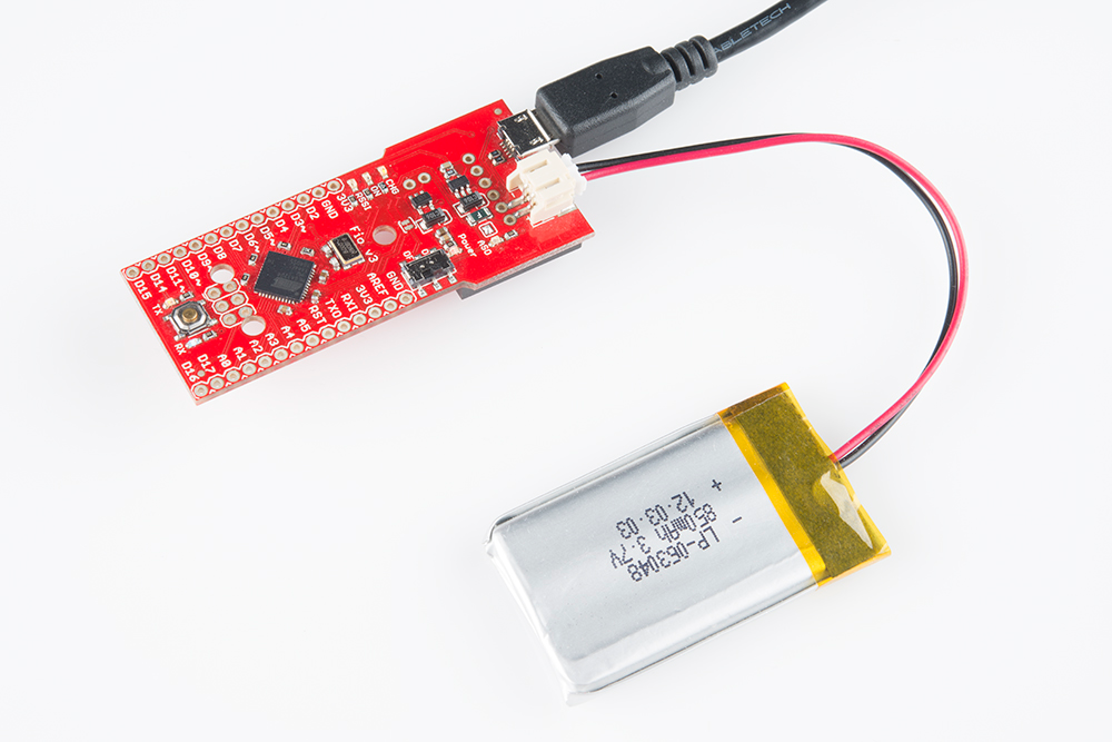
The 'CHG' LED will indicate the status of the battery charge. If it's on, the battery is still charging. Once the 'CHG' LED goes off, the battery is fully charged.
The charge circuit is programmed to charge the battery at 500mA, so, to be safe, the battery should be no smaller than 500mAH in capacity.
Connecting An XBee
The XBee-footprint connectors on the bottom of the Fio v3 are what make it so unique. This product is designed to provide a simple interface between Arduino and XBee, as such a few of the XBee pins come wired up to the ATmega32U4. Most significantly, the serial interfaces of both devices are wired -- the XBee's 'DOUT' pin is connected to the ATmega32U4's 'RX', and 'DIN' is connected to 'TX'.
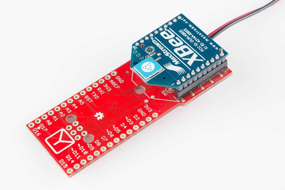
XBee's are controlled and configured over a serial interface. To learn more about using XBee's check out their datasheet and various tutorials for help getting started with these awesomely simple wireless transceivers.