Preassembled 40-pin Pi Wedge Hookup Guide
 Byron J.
Pin Mapping
Changes With the B+
When the Raspberry Pi foundation introduced the B+, they expanded the GPIO header from 26 to 40 pins. These changes have been carried forward by the A+ and Pi 2 Model B. The connector adds nine more GPIO pins plus the ID_SC and ID_SD pins to identify external peripherals, which you can learn more about in our SPI and I2C tutorial.
Signal Location
The Pi Wedge reorganizes the I/O pins on the Pi, putting similar functions on adjacent pins. The SPI, I2C and UART signals are all grouped near each other.
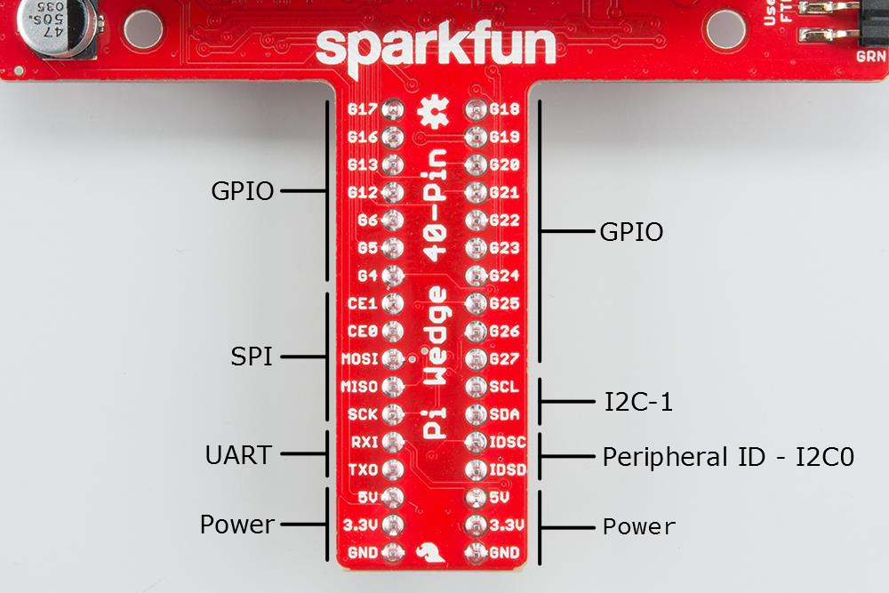
The pins are labeled, though the labels are short, to fit the space available on the PCB. The UART, SPI and I2C pins are marked with their communication bus functions, but they are also available as GPIO pins when configured in that mode.
The following table denotes the assignment of signals on the Pi Wedge, including the peripheral and alternate GPIO assignments where appropriate.
| Wedge Silk | Python (BCM) | WiringPi GPIO | Name | Name | WiringPi GPIO | Python (BCM) | Wedge Silk |
| G17 | 17 | 0 | GPIO17 (GPIO_GEN0) | GPIO18 (GPIO_GEN1) | 1 | 18 | G18 |
| G16 | 16 | 27 | GPIO16 | GPIO19 | 24 | 19 | G19 |
| G13 | 13 | 23 | GPIO13 | GPIO20 | 28 | 20 | G20 |
| G12 | 12 | 26 | GPIO12 | GPIO21 | 29 | 21 | G21 |
| G6 | 6 | 22 | GPIO06 | GPIO22 (GPIO_GEN3) | 3 | 22 | G22 |
| G5 | 5 | 21 | GPIO05 | GPIO23 (GPIO_GEN4) | 4 | 23 | G23 |
| G4 | 4 | 7 | GPIO04 (GPIO_GCLK) | GPIO24 (GPIO_GEN5) | 5 | 24 | G24 |
| CE1 | 11 | GPIO7 (SPI_CE1_N) | GPIO25 (GPIO_GEN6) | 6 | 25 | G25 | |
| CE0 | 10 | GPIO8 (SPI_CE0_N) | GPIO26 | 25 | 26 | G26 | |
| MOSI | 12 | GPIO10 (SPI_MOSI) | GPIO27 (GPIO_GEN2) | 2 | 27 | G27 | |
| MISO | 13 | GPIO09 (SPI_MISO) | GPIO03 (SCL1, I2C) | 9 | SCL | ||
| SCK | (no worky 14) | GPIO11 (SPI_CLK) | GPIO02 (SDA1, I2C) | 8 | SDA | ||
| RXI | 16 | GPIO15 (UART_RXD0) | GPIO0, ID_SC (I2C ID SC EEPROM) | 31 | IDSC | ||
| TXO | 15 | GPIO14 (UART_TXDO) | GPIO1, ID_SD (I2C ID SD EEPROM) | 30 | IDSD | ||
| 5V | 5V | ||||||
| 3.3V | 3.3V | ||||||
| GROUND | GROUND |