Preassembled 40-pin Pi Wedge Hookup Guide
Logic Levels And Power
Logic Levels
The Pi uses 3.3V logic levels, which are not 5V tolerant. Many peripheral devices are capable of running at 3.3V, but in the case that you need to interface with 5V devices, use a level shifter, such as the TXB0104 breakout.
Communications
The signals on the 6-pin FTDI header are also limited to 3.3V logic levels. Be sure to use it with a 3.3V FTDI module, and not a 5V one.
Power
Understanding the Pi's power supply is critical to using it successfully, particularly when building it into a larger system.
The Raspberry Pi B+ is more efficient than it's predecessors, as it replaces the former chain of linear power regulators with switching regulators.
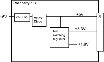
The most recently published schematics are for the Raspberry Pi B+, and we're assuming that the Pi2 model B and A+ are similar. Inspecting those schematics, we see that 5V comes into the the board via connector J1 - it's a micro USB connector, but only the power and ground pins are connected. The 5V coming from this connector passes through a fuse and a transistor circuit that protects against power polarity mishaps, then continues around the board without any further regulation. The 5V connections on the Pi Wedge come straight from this line.
On the B+, the 5V goes to a dual switching regulator that further reduces it to 3.3V, and 1.8V. The regulated 3.3V is present on the I/O connector.
There are several power strategies that can be applied in a Pi deployment, depending on the overall needs and availability.
Power Through the GPIO Connector
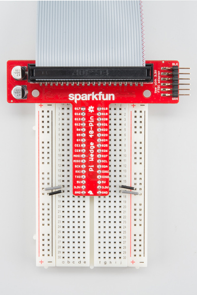
The most obvious strategy for powering small external circuits is to get power directly from the GPIO connector. To power small circuits on your breadboard, you can run jumpers from the 5V or 3.3V and Ground pins on the wedge to the power rails on the breadboard.
While this is the most immediate way to access power, it only extends to small circuits. The B+ itself is limited to 2A total from the 5V line, most of which is needed by the B+ itself. The stated limit for the 3.3V pins is 50 mA.
If you're developing external circuitry, and the Pi resets when you're testing it, you may be exceeding the current limits. We saw this exact situation arise as we added SPI controlled 7-segment LED displays - if we illuminated one too many segments, the system crashed. For circuits with higher power draw, we'll need to explore some alternatives.
Daisy Chaining
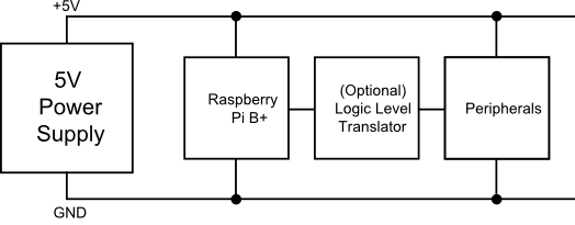
The next power option is to connect each section of the circuit directly to the power supply. This means that the peripherals aren't constrained by the current limits of the fuses and regulators on the Pi itself.
For peripherals that use 5V logic, they should also include 3.3V/5V logic level translation.
Back Power Through J8
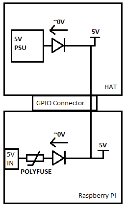
As described above, a simple deployment can power peripherals via the 5V and 3.3V pins of J8, but it's also possible to apply power to the Pi via those lines. The Pi Foundation call this "back powering", and they have a number of recommendations for it's implementation.
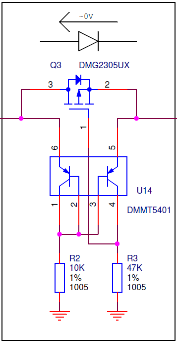
The first recommendation is to duplicate the fuse and MOSFET + BJT power protection circuit as seen on the Pi itself. This circuit is a variant on the "ideal diode" circuit.
It serves several purposes:
- Under ordinary circumstances, with power coming in via the micro-USB plug, the MOSFET is biased fully on, so there is only minimal voltage drop across it, where a typical Schottky or Silicon diode would drop 0.3V or more.
- Second, it prevents power from flowing if the power polarity at the micro-USB plug is incorrect.
- Third, if the board is powered via J8, it prevents power from being drawn from J1, to prevent contention if two supplies are present at the same time.
The other recommendation is that the HAT needs to be able to provide 5V, +/- 5%, with at least 1.3 A available for the Pi.
