Preassembled 40-pin Pi Wedge Hookup Guide
 Byron J.
 Assembly
Contents
The Preassembleed Pi Wedge comes with the Wedge PCB, and a 40-pin ribbon cable.
Connection
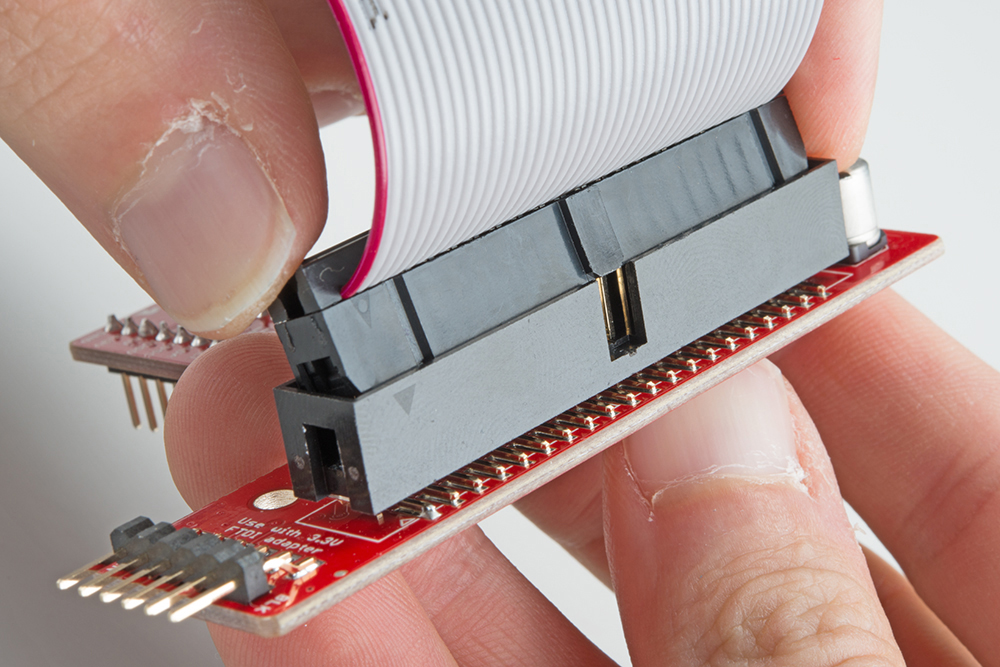
The 40-pin ribbon cable is used to connect the wedge to the Pi. This cable is polarized — notice that the pin 1 marking is very subtle. On the Pi Wedge PCB end, the tooth on the cable will interface with the notch in the shrouded header. Insert the IDC cable into the Pi Wedge's polarized connector so that the cable extends away from the breadboard connection.
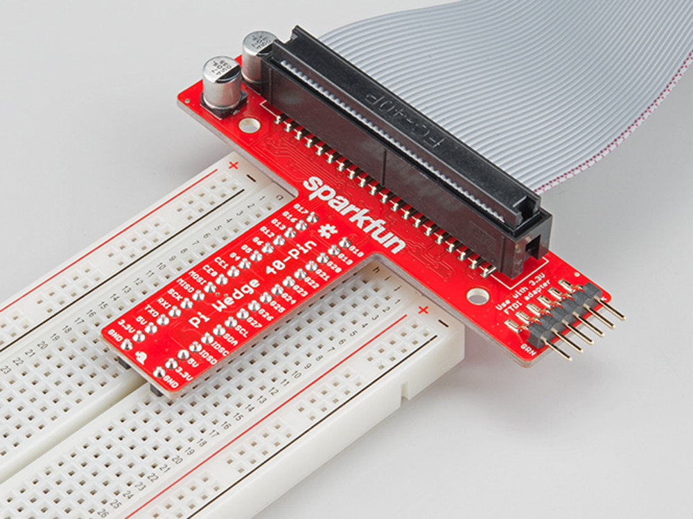
Insert the Wedge into the center of the breadboard so that each pin has their own row.
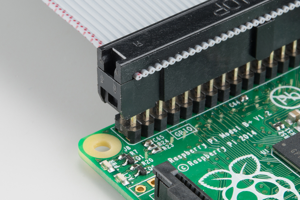
The header on the Pi itself doesn't have anything to help guarantee the alignment. You'll need to take care that it gets connected properly. Pin 1 on the Pi is marked with a dog-eared corner on the silkscreened rectangle. The ribbon cable connector is embossed with (a barely visible) small triangle that marks pin 1. The first pin is also coded on the wire, such as the red markings in the photo below (though it may also be another color, such as black or dark blue). Insert the IDC cable to the Pi so that the cable extends away from the Pi.
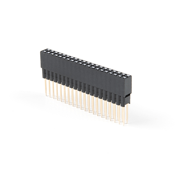
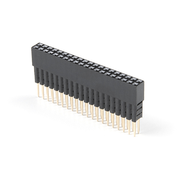
The extension header with 9.80mm pin length [ PRT-16764 ] is useful when sandwiching a PCB between a Pi and HAT. The header can also be used to sandwich a board betwen the Pi and Pi Wedge's IDC cable. The extension header with 7.30mm pin length [ PRT-16763 ] uses three plastic spacers which cover the pins more when using a HAT or the Pi Wedge's IDC cable.
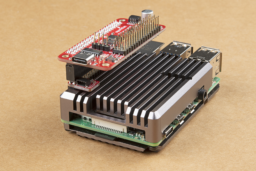 |
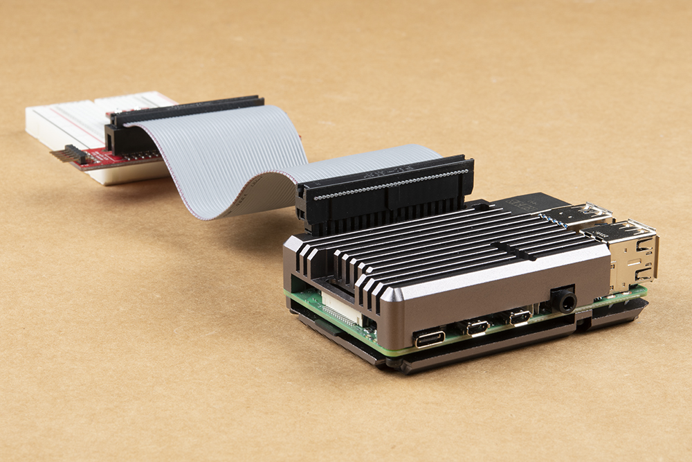 |
| Extension Header with 9.80mm Pin Length is Used to Help Stack the Qwiic SHIM and Pi Servo HAT on a Pi 4 with Heat Sink | Extension Header with 7.30mm Pin Length is Used to Help Connect the Pi Wedge's IDC Cable to the Pi 4 with Heat Sink |
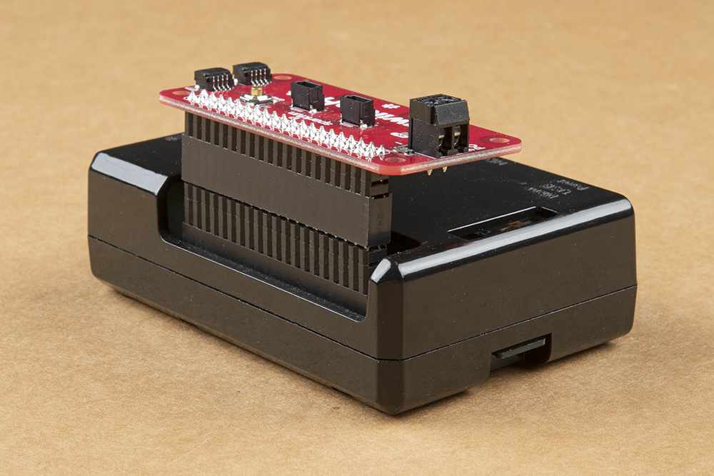
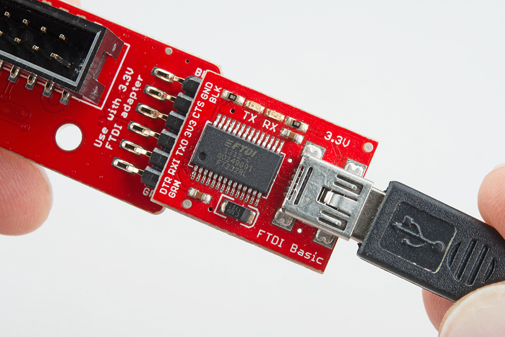
If you decide to connect to the Pi using serial, you can insert a 3.3V FTDI to the Pi Wedge. The FTDI connector needs to be aligned correctly. Be sure to match up the "GRN" and "BLK" markings on both boards.
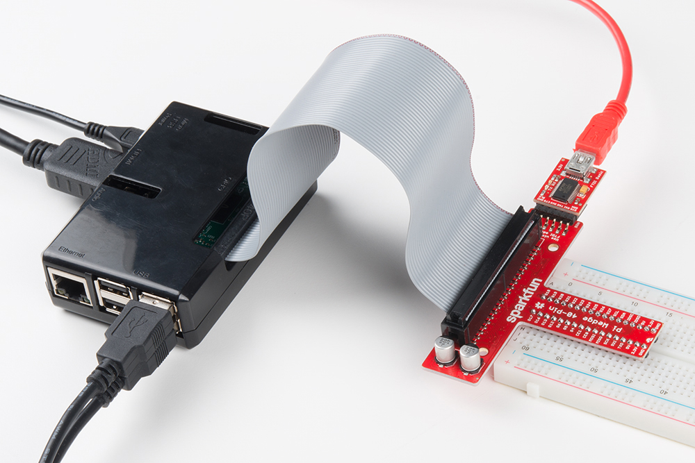
Your setup will look similar to the image below. In this case, we used a Pi 3 in an enclosure.
In the next section, we'll explore how the signals from the Pi are mapped to the Wedge.