OpenLog Artemis Hookup Guide
 Nate,
Nate,  bboyho,
  PaulZC
Hardware Overview
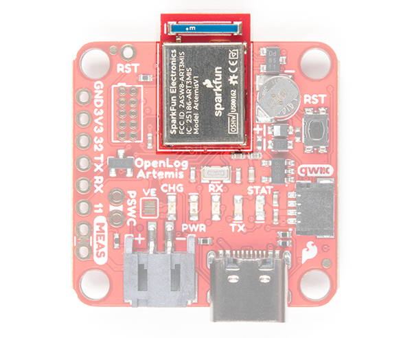
Artemis
The Artemis module is the world's first open source hardware RF processor module. A surprising amount of power can be packed into 10x15mm! Based around the Apollo 3 ARM Cortex-M4F from Ambiq Micro, it runs at 48MHz but with low power consumption. It comes with Bluetooth Low Energy (BLE) wireless communication built-in and we plan to upgrade the OLA to support wireless sensing in the coming months. (Don’t forget: it is really easy to upgrade the OLA firmware. But we’ll get to that in a moment!).
Ambiq, the manufacturer of the Apollo3, has done years of research into something they call Sub-threshold Power Optimized Technology (SPOT™). This is a fancy description of a power saving technique that works by lowering the logic level voltages necessary to indicate a 1 or a 0. By doing so at the silicon level, Ambiq has managed to eke out a 48MHz processor which can draw less than half a milliamp.
The Artemis has a built-in Bluetooth 5.0 radio capable of transmitting up to 4dBm which should get you about 70m transmission distance. We’ve seen successful RSSI checks at over 200ft.
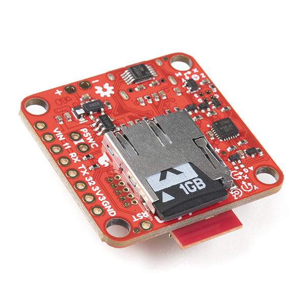
microSD
OpenLog uses common microSD cards to record clear text, comma separated files. Flip over the OLA and you’ll see the latching microSD card socket. You probably already have a microSD card laying around but if you need any additional units, we have plenty in the store. The OLA can use any size microSD card and, as of firmware version 1.11, supports exFAT cards in addition to FAT32. Please ensure your SD card is formatted correctly; we recommend the SD Association Formatter.
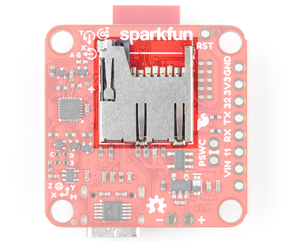
Slide in your formatted SD card and it will click neatly into place. The edge of the SD card will line up with the edge of the circuit board when it is inserted correctly.
As of firmware v1.6, the log file metadata (create and access timestamps) are now set correctly using the OLA’s Real Time Clock. The files on the SD card can also be accessed via the USB terminal interface. A new configuration menu allows you to:
- list the files on the card
- delete individual files
- type the contents of an individual file to the terminal
- send / copy an individual file to the serial TX pin
- transfer individual or all files using the ZMODEM protocol
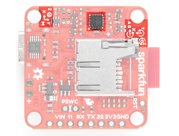
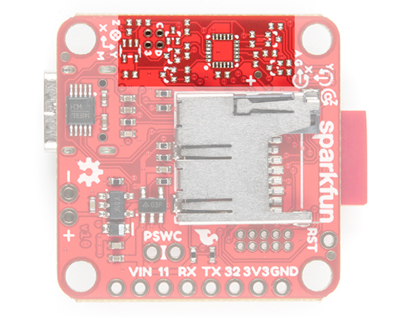
IMU Sensor
Included on every OpenLog Artemis [DEV-16832] is an Inertial Measurement Unit (IMU) for built-in logging of triple-axis accelerometer, gyro and magnetometer data. Whereas the original 9DOF Razor used the old MPU-9250, the OpenLog Artemis uses the latest ICM-20948 capable of nearly 250Hz logging of all 9 axes. Oh, and if that wasn’t enough, it comes with a built-in temperature sensor too. So if you want to use the OLA as a transportation logger, it will do that straight out of the anti-static bag! On every OpenLog Artemis without IMU [DEV-19426], the ICM-20948 IMU sensor and associated circuitry is removed. Users using the OpenLog Artemis without IMU will not be able to log sensor data or configure the ICM-20948 if the sensor is not detected.
 |
 |
| With IMU [DEV-16832] | Without IMU [DEV-19426] |
Power
There are a variety of power and power-related nets broken out to connectors and through hole pads. Below list a few methods of powering the board up. The voltage is regulated down to 3.3V with the AP2112K for the system voltage.
- USB-C
- Single Cell LiPo Battery
- 3V3 Pin
- VIN
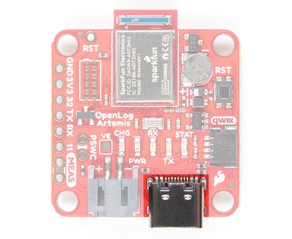
USB-C
Micro-USB is just so passé. Like all recent SparkFun boards, the OLA comes equipped with a USB-C socket which you can use to:
- connect it to your computer for configuration
- or plug in a USB-C power supply
USB-C power supplies are clever beasties and the OLA includes the configuration channel resistors needed to tell the power supply to deliver 5V. So, yes, you can use your USB-C laptop charger as the power source should you need to, even though it normally delivers a much higher voltage. This can also be used to charge the LiPo battery at a default rate of 450mA or program the board.
For customers in North America, our NEMA Raspberry Pi Wall Adapter is a perfect choice. You can also power the OLA from our Lithium Ion Battery Pack - 10Ah (3A/1A USB Ports) but you will need a USB-C cable too:
- Our Reversible USB 2.0 A to C Cable - CAB-15092 will do nicely
- Our USB 3.1 A to C Cable - CAB14743 is a good choice too
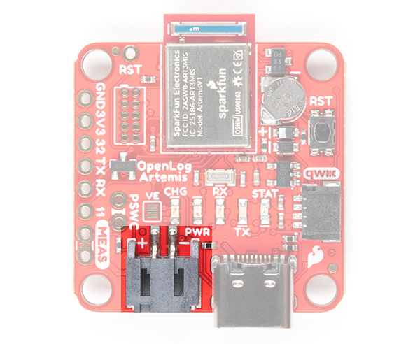
LiPo Battery
But of course you’re going to want to use the OLA to log sensor data while on the move too. You can connect one of our standard single cell LiPo batteries to the OLA and power it for hours, days or weeks depending on what sensors you have attached and how often you log data. The OLA has a built-in charger too which will charge your battery at 450mA when USB-C is connected. Please make sure your battery capacity is at least 450mAh (0.45Ah); bad things will happen if you try to charge our smallest batteries at 450mA. Underneath the JST connector the pins are broken out if you decide to solder a single cell LiPo battery directly to the board.
 |
 |
| JST Connector for Single Cell LiPo Battery | VBATT and GND Pins |
3V3 Pin
For those going the old school route, you can also solder directly to the 3V3 and GND pin to provide power if your application has regulated 3.3V.
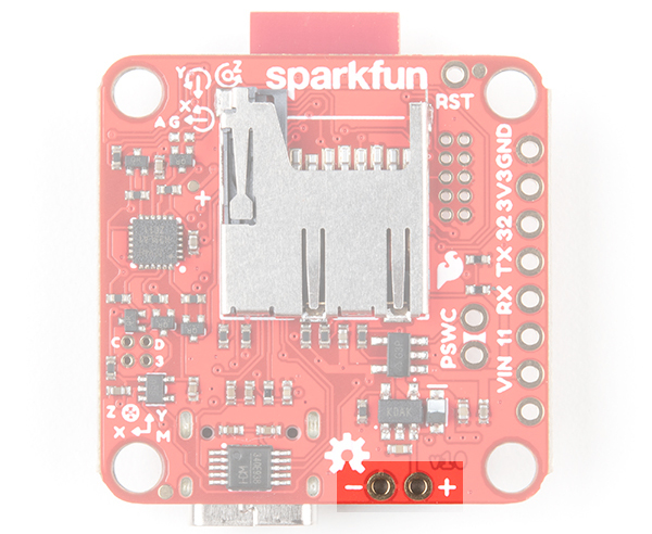
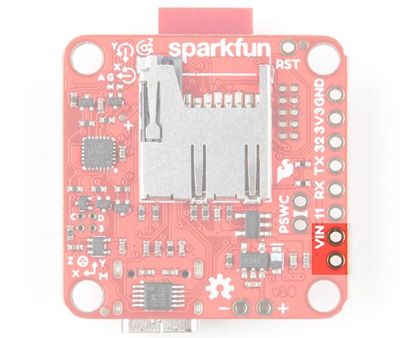
VIN Pin
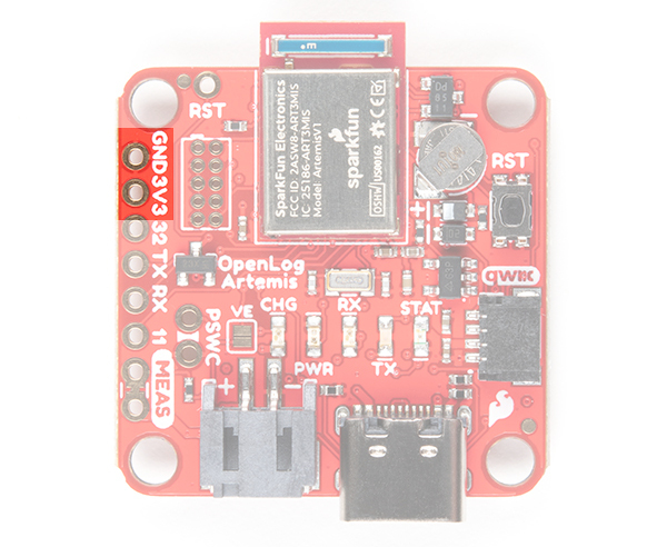
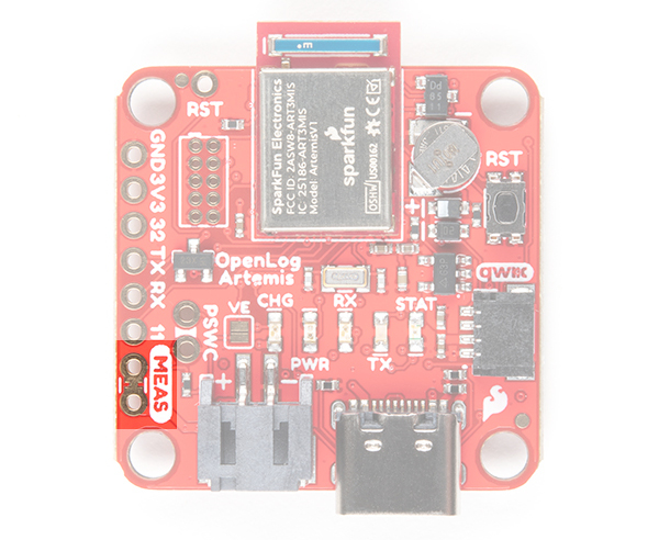
On the back of the board, you will notice that there is a pin labeled VIN. We don’t recommend it, but you can also feed in external power (recommended operating voltage of 6.0V Maximum) via the VIN pin next to breakout pin 11. We don’t recommend it because there is no protection diode between this pin and USB-C 5V power. If you have VIN and USB-C connected at the same time, bad things could happen. If VIN is your only option then we recommend cutting the MEAS jumper to isolate VIN from USB 5V and the LiPo.
 |
 |
| MEAS Pin | MEAS Pins connected to VIN and 5V USB pin |
CH340 USB-to-Serial Converter
On the other side of the USB-C connector is a CH340 USB-to-Serial Converter. The chip can be used to send serial data to your computer or upload new firmware with the Artemis Firmware Uploader.
The driver should automatically install on most operating systems. However, there is a wide range of operating systems out there. You may need to install drivers the first time you connect the chip to your computer's USB port or when there are operating system updates. For more information, check out our How to Install CH340 Drivers Tutorial.
How to Install CH340 Drivers
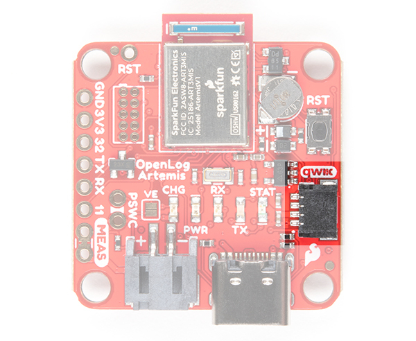
Qwiic and I2C
SparkFun's Qwiic Connect System uses 4-pin JST connectors to quickly interface development boards with I2C sensors and more. No soldering required and there's no need to worry about accidentally swapping the SDA and SCL wires. The Qwiic connector is polarized so you know you’ll have it wired correctly every time, right from the start. Qwiic boards are daisy chain-able too so you can connect multiple sensors to the OLA and log readings from all of them.
Sometimes you might want to connect more than one of the same type of sensor to the OLA. On the I2C bus, each device needs to have a unique address. On many of our boards, there are jumpers links which you can use to change the address and some have addresses that can be configured in software. But there are some where you cannot change the address. The solution is to use one of our Qwiic Mux Breakouts which will allow you to connect multiple devices with the same address to the OLA.
The OLA includes a dedicated 3.3V regulator for the Qwiic connector. This has several advantages including:
- the OLA can completely power-down the I2C sensors during sleep to prolong your battery life
- there’s no risk of the Qwiic bus gulping too much current and causing problems for the Artemis
The I2C pins are also broken out on small PTH pins on the back of the board. Keep in mind that these are not standard breadboard sized PTH pins so you will need some thin wires to connect.
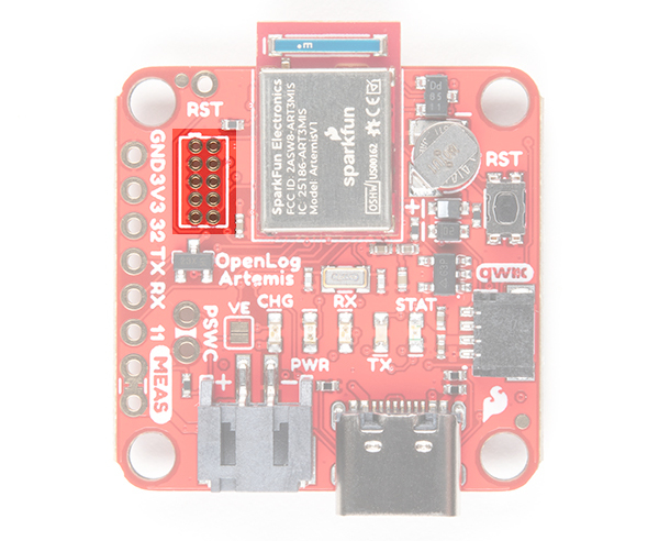
Breakout Pins
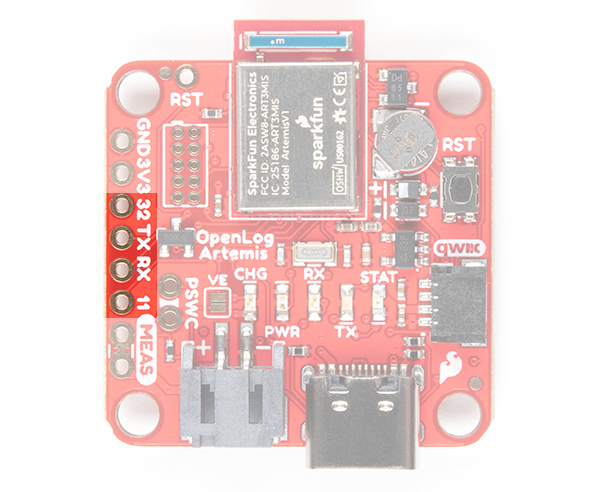
In addition to logging IMU and sensor data, OpenLog Artemis can also log serial streams and analog voltages! You will find the breakout pins along the edge of the board:
- 32 - Analog channel 32. Stop logging - pulling this pin to GND will stop the OLA logging if stop logging has been enabled via the configuration menus. As of firmware v1.11, Pin 32 can also be dedicated to the MAX30101 Pulse Oximeter RST signal.
- TX/12 - Analog channel 12. As of firmware v1.6, the sensor data can also be streamed to the Serial TX pin. As of firmware v1.9, the TX pin can also be used for the serial terminal / console.
- RX/13 - Analog channel 13. Serial RX - Connect any serial stream up to 500000bps [1] and the serial data will be automatically logged to a separate log file. As of firmware v1.9, the TX pin can also be used for the serial terminal / console.
- 11 - Analog channel 11. As of firmware v1.6, pin 11 can also be used to trigger logging of the sensor data. When enabled, a change on pin 11 will trigger the reading and logging of the sensor data. The data will be logged on every falling or rising edge, depending on which you have selected. As of firmware v1.11, Pin 11 can also be dedicated to the MAX30101 Pulse Oximeter MFIO signal.
Analog voltages are converted and logged in much the same way as the other sensor values are. Each analog channel can be enabled or disabled. The values can be either a raw ADC reading (0 to 16,383) or a floating point value (0 to 2.0V)
Serial communication is 3.3V. You will need an adapter if you need to log old-school RS232 data which uses higher voltages.
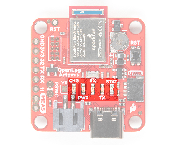
LEDs
There are 5x LEDs on the board:
- CHG - This LED indicates that the LiPo battery is charging. It turns off once the battery is fully charged.
- PWR - The power indicator. This illuminates during normal operation, but can be disabled during sleep to save current. (No jumper links to cut here!)
- RX/TX - These LEDs indicate USB-C serial traffic.
- STAT - This is a general status LED, controlled in software. It is currently used to indicate when the OLA is taking measurements and writing data to the SD card.
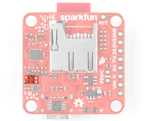
Jumpers
There are two jumpers on board:
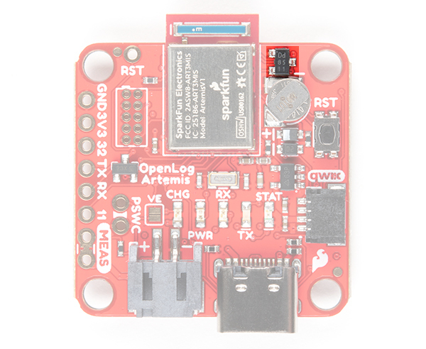
- VE - Voltage Enable. By default, this jumper is open. Experimental: close this jumper to give the Artemis digital control of the voltage regulator. We have included this as a feature for advanced users who may want to experiment with very low power consumption. See “Low Power Considerations” for further details.
- MEAS - By default, the jumper is closed. You can cut this jumper to measure the OLA’s current draw from external power.
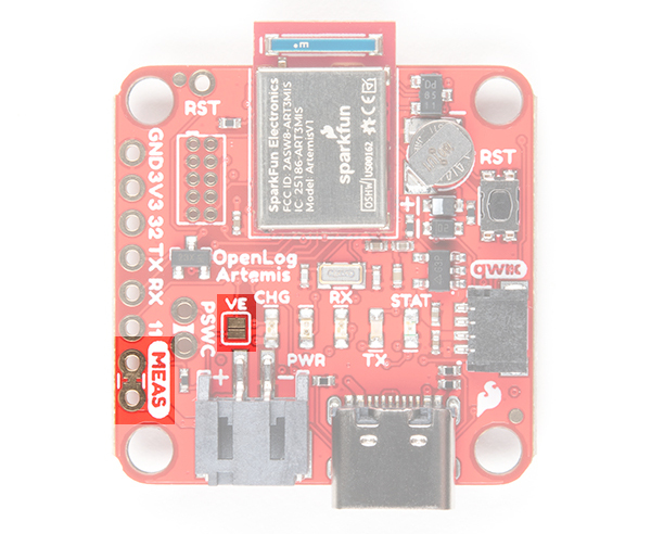 |
|
| VE and MEAS Jumpers | MEAS Pins connected to VIN and 5V USB pin |
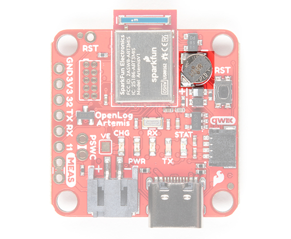
RTC Backup Battery
The Artemis has a built-in Real Time Clock (RTC) which is used to timestamp the logged data. You can set the clock time and date and enable timestamping through the configuration menus. If you have one of our u-blox GNSS modules attached, you can use that to set the RTC. We have included timezone adjustment too!
The OLA has an onboard 1mAh backup battery which is designed to keep the RTC running when the external power is removed. The battery requires 20 minute to charge. The OLA will require a reset to bring it back out of deep sleep when the power is reconnected. See “Low Power Considerations” for further details.
Reset Button and RST Pin
Pressing the miniature reset button, as you might expect, will reset the Artemis. If you have your OLA mounted in an enclosure, you can also attach an external reset switch too. Any Single Pole Normally-Open Push-To-Close momentary switch will do. Solder pin headers or wires to the RST and GND breakout pins and connect your external switch to those.
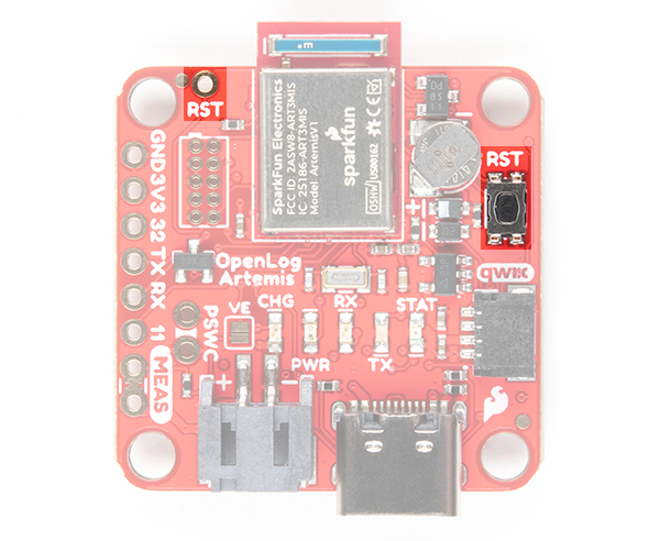
Pressing the reset button will cause the Artemis to restart the firmware. If the OLA was in deep sleep, pressing the reset button will wake it. See “Low Power Considerations” for further details.
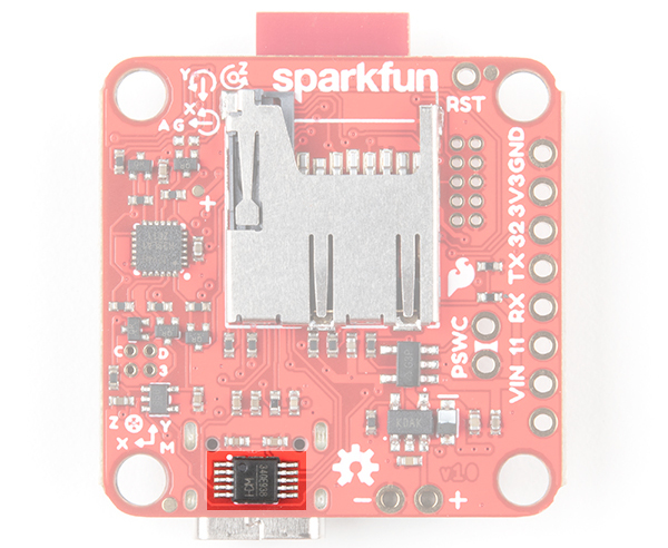
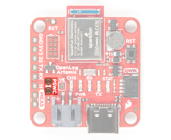
PSWC Pins
The Power Switch (aka PSWC) header can be used to attach an external switch. If you need power control on the outside of an enclosure, solder header pins or wires to the PSWC breakout pins and attach your switch to those. Any Single Pole Single Throw (SPST) toggle switch will do.
When the PSWC header is shorted together by the switch, the enable pin of the 3.3V regulator is pulled low, turning off the power to the OLA. The Artemis will go into deep sleep and draw approximately 18µA of standby current from the RTC battery. The OLA will require a reset to bring it back out of deep sleep when the power is turned back on. See “Low Power Considerations” for further details.
Voltage Divider and Supervisory IC
The OLA has two ways to measure the incoming power voltage. A two-resistor divider allows the Artemis to monitor the power (battery) voltage via one of its analog pins. The OLA code keeps an eye on the battery voltage and will stop logging and put the Artemis into deep sleep when the battery voltage becomes too low. As of firmware v1.6, you can now adjust the low battery threshold voltage via the menus.
The OLA also includes a 3.0V supervisory circuit. If the external power is disconnected or switched off, the supervisor causes an interrupt which forces the Artemis into immediate deep sleep.
While the Artemis is in deep sleep, the back-up battery will keep the RTC running. When power is restored, the OLA will require a reset to bring it back out of deep sleep. See “Low Power Considerations” for further details.
SWD Programming Pins
The single wire debug port is available for advanced users who need low-level debugging tools.
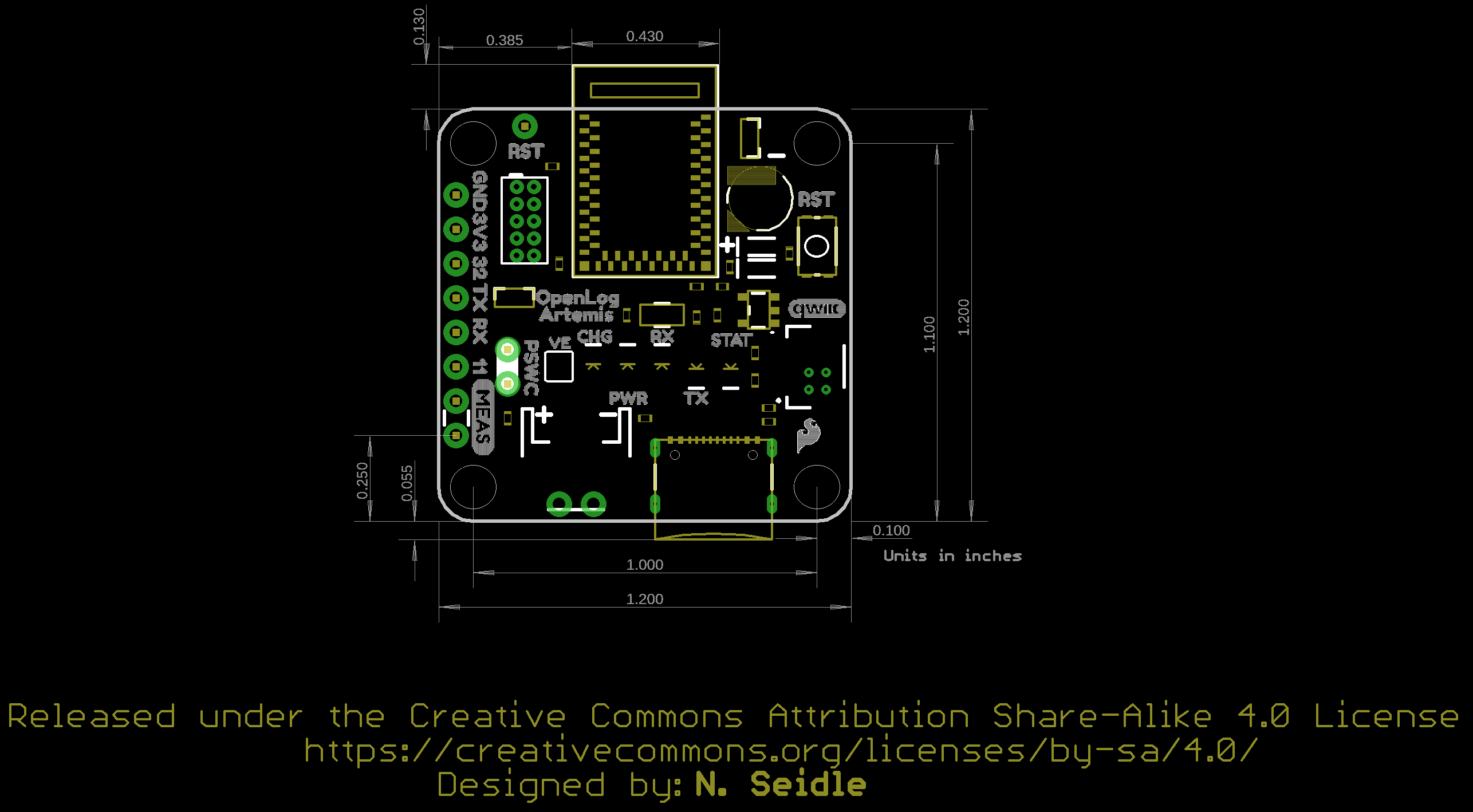
Board Dimensions
The board has four mounting holes. The overall size of the board (including the USB C connector and Artemis module hanging over the edge of the board) is about 1.20"x1.43".