OpenLog Artemis Hookup Guide
Hardware Hookup
microSD Card
If all you want to do is display your sensor readings in a serial terminal or monitor (connected via USB-C) then, strictly, you don’t need to add a microSD card. But of course the whole point of the OLA is that it can log readings from whatever sensors you have attached to microSD card. The data is logged in easy-to-read Comma Separated Value (CSV) text format.
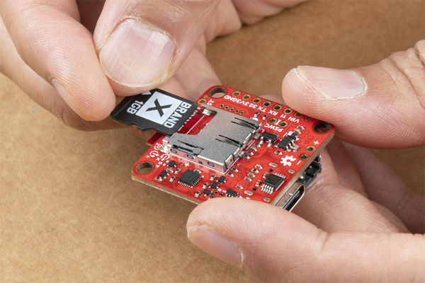
You probably already have a microSD card laying around but if you need any additional units, we have plenty in the store. The OLA can use any size microSD card and, as of firmware version 1.11, supports exFAT cards in addition to FAT32. Please ensure your SD card is formatted correctly; we recommend the SD Association Formatter. Flip over the OLA and you’ll see the latching microSD card socket. Slide in your formatted SD card and it will click neatly into place. The edge of the SD card will line up with the edge of the circuit board when it is inserted correctly.
You should only insert or remove the SD card while the power is turned off or disconnected. Removing the card while the OLA is logging will almost certainly corrupt your data.
After you’ve logged some data, you will find several new files on your SD card:
- dataLog00000.TXT: This is the file that contains the CSV sensor data. We use .TXT as the file type so that your computer can open it in a simple text editor. The contents are all human-readable. But, if you want to, you can rename it as .CSV instead. The file number is incremented for the next logging session.
- serialLog00000.TXT: If you have been using the OLA’s RX pin to log serial data, you will find that data in this file. Again, the file number is incremented if required. (The OLA automatically reuses any files that are zero length, so the file number will only increment once some serial data has been logged.)
- OLA_settings.txt: The OLA’s core settings are configured via the configuration menus and stored in the OLA’s non-volatile “EEPROM” memory. However, a copy is kept on the SD card too in this file. If you don’t have access to a USB-C cable or serial monitor, you can edit this file to change the OLA settings if you need to. They will get loaded and copied into EEPROM next time you power up the OLA.
- OLA_deviceSettings.txt: The settings for each attached sensor are stored in this file. Whenever you attach a new sensor or change the sensor settings via the configuration menus, this file gets updated. Again the file is human-readable and can be edited in a text editor should you need to.
Qwiic Sensors and Muxes
If you are going to attach extra sensors to the OLA, then those need to be connected first before attaching a USB cable. It is a good idea to only attach or disconnect Qwiic sensors when the power is turned off or disconnected. The Qwiic bus is pretty tolerant to “hot swapping”, but: disconnecting a sensor while it is in use will confuse the OLA software; and a new sensor won’t be detected until the firmware restarts.
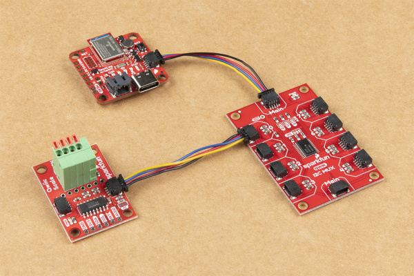
Plug one end of your Qwiic cable into the OLA and plug the other end into your sensor. If you want to add extra sensors, you can simply connect them to each other in a daisy chain. You will need a Qwiic cable for each sensor. Our Qwiic Cable Kit covers all the options
 |
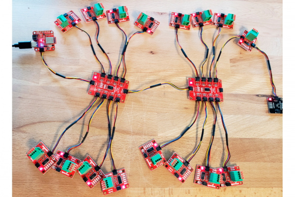 |
| OLA and a Qwiic Sensor/Mux | OLA and several Qwiic Enabled Devices |
Our Qwiic sensors usually all have power indicator LEDs and I2C pull-up resistors. Depending on your application, you may want or need to disable these by cutting the jumper links on the sensor circuit boards. We have a tutorial that will show you how to do that safely.
Sometimes you might want to connect more than one of the same type of sensor to the OLA. On the I2C bus, each device needs to have a unique address. On many of our boards, there are jumpers links which you can use to change the address and some have addresses that can be configured in software. But there are some where you cannot change the address - the NAU7802 Qwiic Scale being one example. The solution is to use one or more of our Qwiic Mux Breakouts to allow you to connect multiple devices with the same address to the OLA.
- You can attach up to eight Qwiic Muxes to the OLA
- Each Mux must have a unique address (set via the solder split pad links)
- The Muxes must be daisy-chained Main to Main (you cannot connect Muxes to Mux ports in a star configuration)
- Non-unique sensors should all be connected to individual Mux ports (connecting a non-unique sensor to the Main Qwiic bus will prevent any duplicates from being detected)
MAX30101 Pulse Oximeter
If you want to log biometric data from the MAX30101 Pulse Oximeter and Heart Rate Sensor, you will need to:
- Connect the Oximeter to the Qwiic bus using a standard Qwiic cable
- Connect the RST pin on the Oximeter to Pin 32 on the OLA
- Connect the MFIO pin on the Oximeter to Pin 11 on the OLA
- Enable detection of the Oximeter via the Configure Attached Devices menu
We have headers and jumper wires in the store which will help here.
USB Cable
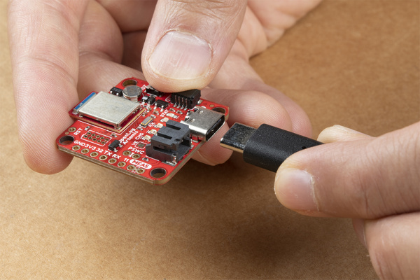
The USB-C connector provides power to the OLA and acts as a serial interface for configuration and data display.
If you are going to use a microSD card to store your data, and why wouldn’t you, then insert that first before attaching your USB cable. You should only insert or remove the SD card while the power is turned off or disconnected. Removing the card while the OLA is logging will almost certainly corrupt your data.
Likewise, it is a good idea to only attach or disconnect Qwiic sensors when the power is turned off or disconnected. The Qwiic bus is pretty tolerant to “hot swapping”, but: disconnecting a sensor while it is in use will confuse the OLA software; and a new sensor won’t be detected until the firmware restarts.
Depending on what ports your computer has available, you will need one of the following cables:
Use the cable to connect your OLA to your computer and you will see the LEDs light as the OLA starts up. The red PWR power LED will come on. The blue STAT status LED will come on too for a second or two while the OLA configures itself. It will flash while data is being logged to SD card. The yellow and green TX and RX LEDs will flash whenever there is serial traffic on the USB interface. If you have jumped the gun and have a LiPo battery already connected, the yellow CHG charging LED may light up too.
If the STAT LED does not light up, your OLA is probably in deep sleep following a previous logging session. Pressing the RST reset button will wake it. See “Low Power Considerations” for further details.
You’ll find full instructions on how to configure the OLA in the next section.
LiPo Battery
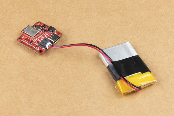
Now is a good time to attach a LiPo battery, if you want the OLA to keep logging when you disconnect USB-C.
You can connect one of our standard single cell LiPo batteries to the OLA and power it for hours, days or weeks depending on what sensors you have attached and how often you log data. The OLA has a built-in charger too which will charge your battery at 450mA when USB-C is connected. Please make sure your battery capacity is at least 450mAh (0.45Ah); bad things will happen if you try to charge our smallest batteries at 450mA. The yellow CHG charging LED will light up while the battery is charging and will go out once charging is complete.
Please note that if you configure your OLA via USB-C and then disconnect the USB cable before attaching your battery, the OLA will go into deep sleep and will need a reset to wake it. You can prevent this by connecting the battery before removing your USB cable.
Serial Logging
Serial communication has been around since 1960. Original protocols like RS232 used much higher voltages to carry data over long cables. Serial data is of course still in use today but, like many Arduino boards, the OLA only supports 3.3V serial communication. Please see our tutorial for full details.
If you feed serial data onto the RX breakout pin, the OLA will automatically log it to a separate file on the SD card. This can be useful if you want to log e.g. serial data from a GNSS module. You will need to set the serial baud rate (speed) to the correct value using the configuration menus. Please see the next section for full details.
