MicroMod Weather Carrier Board Hookup Guide
Introduction
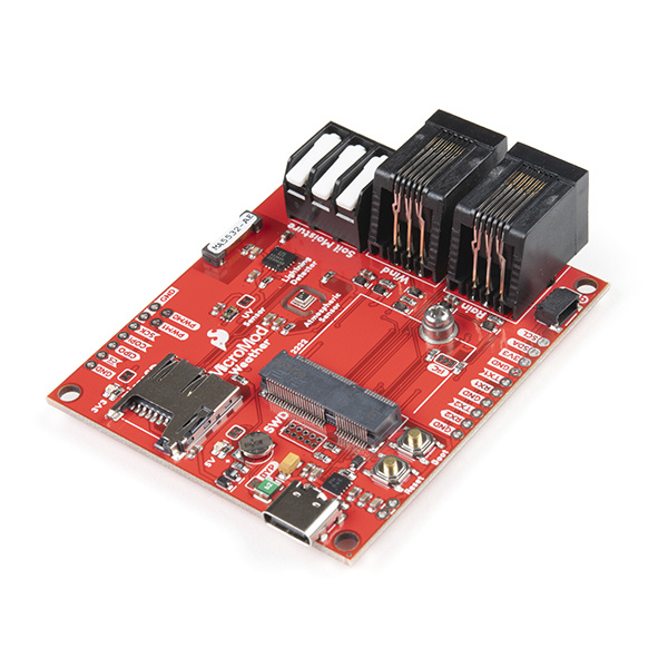
Introducing the MicroMod Weather Carrier Board! This nifty little weather station board works with all SparkFun MicroMod Processors so you can customize your weather station project to fit your needs.
SparkFun MicroMod Weather Carrier Board
SEN-16794The Weather Carrier Board includes three sensors: the BME280 Temperature, Pressure and Humidity sensor, the VEML6075 UV light sensor and the AS3935 lightning detector. Along with these on-board sensors there is a 3-pin latch terminal to add an external soil moisture sensor as well as a pair of RJ11 jacks to plug in the wind and rain sensors included with our Weather Meter Kit. To top it all off there is a microSD card slot so you can plug in an SD card to log all of that glorious weather data!
Required Materials
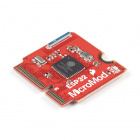
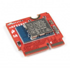
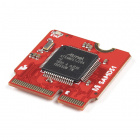
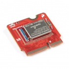
Like all of our MicroMod Carrier Boards, there is no processor included but instead you can plug in a processor of your choice to the MicroMod M.2 connector on the carrier. Here are few options to choose for your processor:
You'll also need a USB-C cable to connect the Carrier Board to your computer and if you want to add some Qwiic breakouts to your MicroMod project you'll want at least one Qwiic cable to connect it all together. Below are some options for both of those cables:
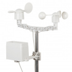
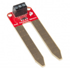
If you want to take full advantage of the features of the Weather Carrier Board you will also need a SparkFun Soil Moisture Sensor, the Weather Meter Kit and a microSD card:
microSD Card - 16GB (Class 10)
COM-15051Suggested Reading
The SparkFun MicroMod ecosystem offers a unique way to allow users to customize their project to their needs. Do you want to send your weather data via a wireless signal (e.g. Bluetooth or WiFi)? There's a MicroMod Processor for that. Looking to instead maximize efficiency and processing power? You guessed it, there's a MicroMod Processor for that.
If you aren't familiar with the MicroMod ecosystem, we recommend reading here for an overview.
 |
Before you get started with the Weather Carrier Board, you may want to read through the Hookup Guide for your chosen MicroMod Processor. MicroMod Processor Hookup Guides can be found on the processors' product pages. We also recommend reading through the following tutorials if you are not familiar with the concepts covered in them:
Serial Peripheral Interface (SPI)
I2C
Serial Terminal Basics
Getting Started with MicroMod
If you're interested in learning more about each of the sensors included on the Weather Carrier Board, take a look at their dedicated Hookup Guides:
Qwiic UV Sensor (VEML6075) Hookup Guide
SparkFun AS3935 Lightning Detector Hookup Guide (v20)
Qwiic Atmospheric Sensor (BME280) Hookup Guide
Hardware Overview
In this section we'll cover the various hardware, sensors and adjustable solder jumpers on the MicroMod Weather Carrier Board, the external sensor connections and the pinout of the Carrier Board for a detailed look at how it connects to your chosen MicroMod Processor.
Common Components
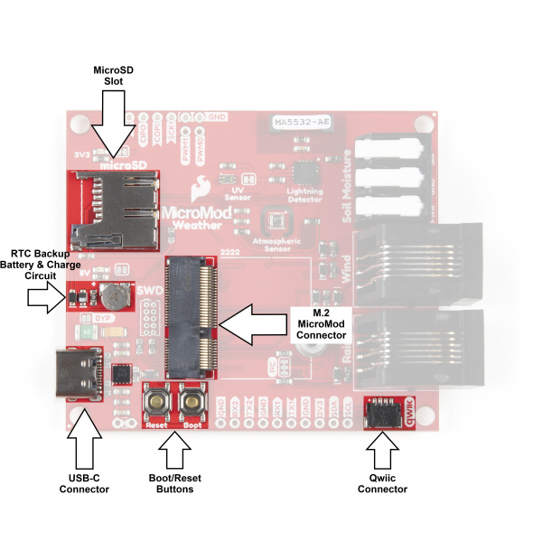
Most SparkFun MicroMod Carrier Boards will have some common components and all MicroMod Carrier Boards will have the keyed M.2 MicroMod Connector to plug your processor into. The photo and list below outline some of the components you can expect on the Weather Carrier Board and most other SparkFun MicroMod Carrier Boards.
- M.2 MicroMod Connector - This special keyed M.2 connector lets you install your MicroMod Processor of choice on your Weather Carrier Board.
- USB-C Connector - Connect to your computer to program your processor and also can provide power to your MicroMod system.
- 3.3V Regulator - Provides a regulated 3.3V and sources up to 1A.
- Qwiic Connector - The standard Qwiic connector so you can add other Qwiic devices to your MicroMod system.
- Boot/Reset Buttons - Push buttons to enter boot mode on processors and to reset your MicroMod circuit.
- RTC Backup Battery & Charge Circuit - 1mAh backup battery for the Real-Time Clocks on MicroMod Processors that have a built-in RTC. Receives charge voltage from 3.3V.
- microSD Slot - Insert a microSD card formatted to FAT32 here to log your weather data.
Weather Station Sensors and External Sensor Connections
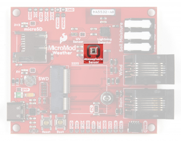
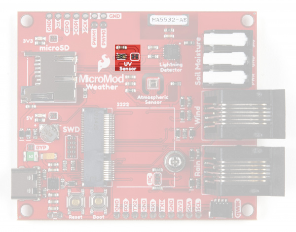
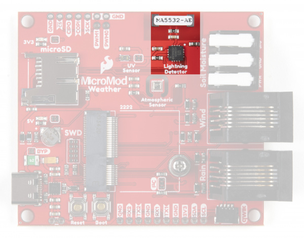
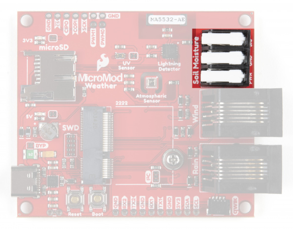
As we mentioned in the introduction, the board comes with a BME280 Temperature, Pressure and Humidity Sensor, a VEML6075 UV Light Sensor and a AS3935 Lightning Detector. Along with those on board sensors there is a three pin latch terminal for a soil moisture sensor as well as a pair of RJ11 jacks for connecting wind and rain meters.
The three on board sensors paired with the external sensors allows for a powerful and customizable weather tracking tool.
BME280 Temperature, Pressure and Humidity Sensor
The BME280 Atmospheric Sensor from Bosch is the heavy lifter of the Weather Carrier Board. The BME280 is a highly-accurate, digital environmental sensor that measures ambient temperature, relative humidity and barometric pressure.
The BME280 measures humidity from 0 to 100% with an absolute accuracy of ±3 %RH (from 20-80%RH), temperatures between 0°C to 65°C with an absolute accuracy of ±0.5-1.5°C (full temperature range is -40°C to 85°C) and atmospheric pressures between 300 to 1100hPa with an absolute accuracy of ±1hPa (relative accuracy of ±0.12hPa). The I2C address of the BME280 is 0x77.
For detailed information on the sensor's functionality and characteristics, refer to the BME280 Datasheet or our Hookup Guide for the SparkFun Qwiic Atmospheric Sensor (BME280).
VEML6075 UV Sensor
The VEML6075 UV light sensor from Vishay Semiconductors measures UVA (320-400 nm, peak @365 ±10nm ) and UVB (228-320 nm, peak @330 ±10nm) irradiance so you can calculate the UV Index at your Weather Station. Example 4 - Calculate UVI in the SparkFun VEML6075 Arduino Library demonstrates how to calculate that index using this sensor.
The VEML6075 has a UVA resolution of 0.93 counts/µW/cm2 and a UVB resolution of 2.1 counts/µW/cm2. The I2C address is 0x10.
For more information about this UV sensor, refer to the VEML6075 datasheet or our Hookup Guide for the SparkFun Qwiic UV Sensor (VEML6075).
AS3935 Lightning Detector
The AS3935 Lightning Detector from AMS can detect lightning strikes up to 40km away with an accuracy of up to 1km from the storm front. The specially-tuned antenna picks up lightning events in the 500kHz band and a built-in algorithm helps check the incoming signal pattern to reject potential man-made disturbers such as DC/DC converters in large appliances.
The AS3935 Lightning Detector is connected to the primary SPI bus and Chip Select (CS) for the AS3935 is tied to G1/Bus1 (MicroMod pad 42).
For in-depth information about the sensor, refer to the AS3935 Datasheet or our Hookup Guide for the SparkFun Lightning Detector Breakout.
Soil Moisture Sensor Latch Terminal
The three-pin latch terminal makes it easy to connect a Soil Moisture Sensor to your Weather Carrier Board. The soil moisture sensor is a handy addition to the Weather Carrier Board if you are using it in something like a greenhouse environment to keep an eye on your soil and, with some slick coding, you could even turn an irrigation system on or off depending on the sensor's measurements.
The Soil Moisture Sensor has two large coated pads that act as prongs for what is essentially a large variable resistor. The sensor takes advantage of a simple concept of moist soil being more conductive than dry soil so as more water is added to the soil, the resistance of the circuit drops and the SIG output increases.
Power (3.3V) for the sensor is provided by G0 (MicroMod pad 40) allowing you to turn it on and off easily (continuous power is not recommended for the soil moisture sensor) and the Signal output is tied to A0 (MicroMod pad 34).
If you are looking for some inspiration for an automated watering project, check out our Product Showcase Video and the Soil Moisture Sensor Hookup Guide.
Wind and Rain RJ11 Connectors
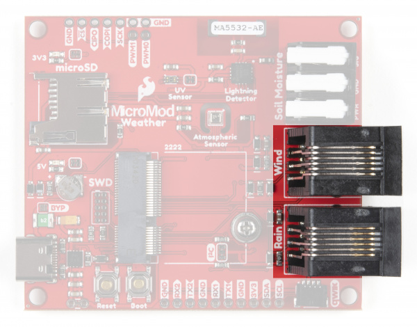
The two RJ11 connectors allow you to connect the wind and rain sensors included with our Weather Meters Kit to monitor wind speed, wind direction and rainfall. These two sensors are great additions to an outdoor Weather Carrier Board setup to get a more complete view of weather in the area.
The Weather Meters Kit includes an anemometer to measure wind speed, a wind vain to determine wind direction and a self-emptying tipping bucket collector to monitor rainfall. The anemometer outputs a digital signal tied to D0 (MicroMod pad 10). The wind vain outputs an analog signal relative to its position tied to A1 (MicroMod pad 38). The rainfall detector outputs a digital signal to D1 (MicroMod pad 18).
For help assembling and testing your Weather Meters Kit, check out our Weather Meter Hookup Guide.
Plated Through-Hole Headers
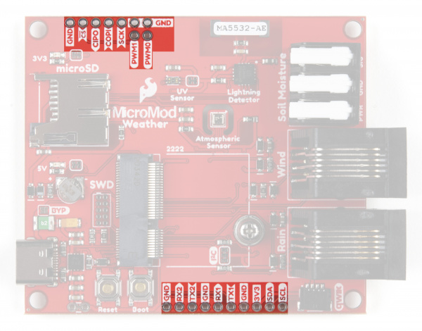
The Weather Carrier Board also routes several pins from a connected MicroMod Processor to a pair of plated through-hole (PTH) headers.
On the "North"/Top of the board, the primary SPI bus is routed to a PTH header (the CS pin on this header is routed to G2/BUS2), a trio of Ground pins and both PWM1 & PWM0 if users wish to solder components that can use pulse-width modulation.
The "South"/Bottom of the board features both Serial UARTs (UART1 & UART2), another pair of Ground pins as well as 3.3V and SDA/SCL from the primary I2C bus if users prefer to have a soldered connection for I2C devices instead of the Qwiic connector.
Solder Jumpers
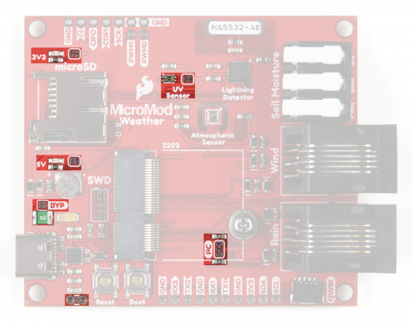
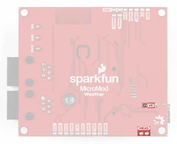
There are a total of seven adjustable solder jumpers on the MicroMod Weather Carrier Board labeled I2C, MEAS, BYP, VE, UV, 5V and 3V3. The table below briefly outlines their functionalities:
| Jumper Name/Label | Description | Default State |
|---|---|---|
| I2C Pull-Up/I2C | Pulls the SDA/SCL lines to 3.3V via two 2.2K Ohm resistors | CLOSED |
| Measure/MEAS | Open this jumper to probe the current draw at the 3.3V output of the regulator. For help measuring current, take a look at our How to Use a Multimeter tutorial. | CLOSED |
| Bypass/BYP | The "penny-in-the-fuse" jumper. Bypasses the 6V/2A fuse and nets VIN and V_USB together. Close only if you know what you are doing! | OPEN |
| Voltage Regulator Enable/VE | Voltage regulator control. Close this jumper to control the VREG in low-power applications. | OPEN |
| UV Sensor Power/UV | Connects VDD of the VEML6075 UV Sensor to 3.3V. Open the jumper to disable power to the UV Sensor. | CLOSED |
| VIN LED Power/VIN LED | Connects the 5V/VIN LED to 5V via a 1K Ohm resistor. Open to disable the LED. | CLOSED |
| 3.3V LED Power/3V3 LED | Connects the 3.3V LED to 3.3V via a 1K Ohm resistor. Open to disable the LED. | CLOSED |
 |
 |
MicroMod Pinout
Since this carrier board is designed to work with all of the MicroMod Processors we've included the table below to outline which pins are used so, if you would like, you can compare them to the pinout tables in their respective Hookup Guides.
| AUDIO | UART | GPIO/BUS | I2C | SDIO | SPI | Dedicated |
| M.2 Connector Pin# | MicroMod Pin Name | Weather Station Connection | Description |
|---|---|---|---|
| 1 | GND | GND | Ground plane. |
| 2 | 3.3V | 3.3V | Regulated 3.3V via USB-C. |
| 3 | USB_D+ | Passthrough | USB D+ connection for Processor Board. |
| 4 | 3.3V_EN | 3.3V Enable | Voltage regulator enable input. |
| 5 | USB_D- | Passthrough | USB D- connection for Processor Board. |
| 6 | RESET | RESET Button | Connected to RESET Button. Reset is active LOW |
| 9 | USB_VIN | VIN | Input voltage from USB. |
| 10 | D0 | WSPEED | Digital pin for wind speed. |
| 11 | BOOT | BOOT Button | Connected to BOOT Button. Boot is active LOW. |
| 12 | I2C_SDA | I2C_SDA | I2C data signal for BME280, VEML6075 and other Qwiic/I2C devices. |
| 14 | I2C_SCL | I2C_SCL | I2C clock signal for BME280, VEML6075 and other Qwiic/I2C devices. |
| 17 | UART_TX1 | TX1 | UART1 data output. Tied to TX1 PTH header pin. |
| 18 | D1/CAM_TRIG | RAIN | Digital pin for rain meter signal. |
| 19 | UART_RX1 | RX1 | UART1 data input. Tied to RX1 PTH header pin. |
| 20 | UART_RX2 | RX2 | UART2 data input. Tied to RX2 PTH header pin. |
| 21 | SWDCK | SWDCK | Serial Wire Debug Clock. |
| 22 | UART_TX2 | TX2 | UART2 data output. Tied to TX2 PTH header pin. |
| 23 | SWDIO | SWDIO | Serial Wire Debug I/O |
| 32 | PWM0 | PWM0 | Dedicated PWM0 pin. Broken out to PTH header pin. |
| 34 | A0 | SOIL_MOIST_SIG | Analog input from soil mositure sensor. |
| 38 | A1 | WDIR | Analog input for wind direction. |
| 40 | G0/BUS0 | SOIL_MOIST_PWR | General purpose pin configured for 3.3V output. |
| 42 | G1/BUS1 | LIGHTNING_CS | AS3935 Chip Select. |
| 44 | G2/BUS2 | HEADER_CS | General chip select pin. Tied to SPI PTH header. |
| 46 | G3/BUS3 | LIGHTNING_INT | AS3935 interrupt pin. |
| 47 | PWM1 | PWM1 | Dedicated PWM1 pin. Broken out to PTH header pin. |
| 49 | BATT_VIN/3 | VIN/3 | Divided input voltage for monitoring power supply. |
| 55 | SPI_CS | SD_CS | µSD Chip Select. |
| 57 | SPI_SCK | SPI_SCK | SPI clock signal. |
| 59 | SPI_COPI | SPI_COPI | SPI Controller Out/Peripheral In signal. |
| 61 | SPI_CIPO | SPI_CIPO | SPI Controller In/Peripheral Out signal. |
| 72 | RTC_3V | RTC_3V | 3V output for backup battery charging. |
| Function | Bottom Pin |
Top Pin |
Function | ||||||
|---|---|---|---|---|---|---|---|---|---|
| (Not Connected) | 75 | GND | |||||||
| 3.3V | 74 | 73 | G5 / BUS5 | ||||||
| RTC_3V_BATT | 72 | 71 | G6 / BUS6 | ||||||
| SPI_CS1# | SDIO_DATA3 (I/O) | 70 | 69 | G7 / BUS7 | |||||
| SDIO_DATA2 (I/O) | 68 | 67 | G8 | ||||||
| SDIO_DATA1 (I/O) | 66 | 65 | G9 | ADC_D- | CAM_HSYNC | ||||
| SPI_CIPO1 | SDIO_DATA0 (I/O) | 64 | 63 | G10 | ADC_D+ | CAM_VSYNC | |||
| SPI COPI1 | SDIO_CMD (I/O) | 62 | 61 | SPI_CIPO (I) | |||||
| SPI SCK1 | SDIO_SCK (O) | 60 | 59 | SPI_COPI (O) | LED_DAT | ||||
| AUD_MCLK (O) | 58 | 57 | SPI_SCK (O) | LED_CLK | |||||
| CAM_MCLK | PCM_OUT | I2S_OUT | AUD_OUT | 56 | 55 | SPI_CS# | |||
| CAM_PCLK | PCM_IN | I2S_IN | AUD_IN | 54 | 53 | I2C_SCL1 (I/O) | |||
| PDM_DATA | PCM_SYNC | I2S_WS | AUD_LRCLK | 52 | 51 | I2C_SDA1 (I/O) | |||
| PDM_CLK | PCM_CLK | I2S_SCK | AUD_BCLK | 50 | 49 | BATT_VIN / 3 (I - ADC) (0 to 3.3V) | |||
| G4 / BUS4 | 48 | 47 | PWM1 | ||||||
| G3 / BUS3 | 46 | 45 | GND | ||||||
| G2 / BUS2 | 44 | 43 | CAN_TX | ||||||
| G1 / BUS1 | 42 | 41 | CAN_RX | ||||||
| G0 / BUS0 | 40 | 39 | GND | ||||||
| A1 | 38 | 37 | USBHOST_D- | ||||||
| GND | 36 | 35 | USBHOST_D+ | ||||||
| A0 | 34 | 33 | GND | ||||||
| PWM0 | 32 | 31 | Module Key | ||||||
| Module Key | 30 | 29 | Module Key | ||||||
| Module Key | 28 | 27 | Module Key | ||||||
| Module Key | 26 | 25 | Module Key | ||||||
| Module Key | 24 | 23 | SWDIO | ||||||
| UART_TX2 (O) | 22 | 21 | SWDCK | ||||||
| UART_RX2 (I) | 20 | 19 | UART_RX1 (I) | ||||||
| CAM_TRIG | D1 | 18 | 17 | UART_TX1 (0) | |||||
| I2C_INT# | 16 | 15 | UART_CTS1 (I) | ||||||
| I2C_SCL (I/0) | 14 | 13 | UART_RTS1 (O) | ||||||
| I2C_SDA (I/0) | 12 | 11 | BOOT (I - Open Drain) | ||||||
| D0 | 10 | 9 | USB_VIN | ||||||
| SWO | G11 | 8 | 7 | GND | |||||
| RESET# (I - Open Drain) | 6 | 5 | USB_D- | ||||||
| 3.3V_EN | 4 | 3 | USB_D+ | ||||||
| 3.3V | 2 | 1 | GND | ||||||
| Signal Group | Signal | I/O | Description | Voltage | Power | 3.3V | I | 3.3V Source | 3.3V |
|---|---|---|---|---|
| GND | Return current path | 0V | ||
| USB_VIN | I | USB VIN compliant to USB 2.0 specification. Connect to pins on Processor Board that require 5V for USB functionality | 4.8-5.2V | |
| RTC_3V_BATT | I | 3V provided by external coin cell or mini battery. Max draw=100μA. Connect to pins maintaining an RTC during power loss. Can be left NC. | 3V | |
| 3.3V_EN | O | Controls the carrier board's main voltage regulator. Voltage above 1V will enable 3.3V power path. | 3.3V | |
| BATT_VIN/3 | I | Carrier board raw voltage over 3. 1/3 resistor divider is implemented on carrier board. Amplify the analog signal as needed for full 0-3.3V range | 3.3V | |
| Reset | Reset | I | Input to processor. Open drain with pullup on processor board. Pulling low resets processor. | 3.3V |
| Boot | I | Input to processor. Open drain with pullup on processor board. Pulling low puts processor into special boot mode. Can be left NC. | 3.3V | |
| USB | USB_D± | I/O | USB Data ±. Differential serial data interface compliant to USB 2.0 specification. If UART is required for programming, USB± must be routed to a USB-to-serial conversion IC on the processor board. | |
| USB Host | USBHOST_D± | I/O | For processors that support USB Host Mode. USB Data±. Differential serial data interface compliant to USB 2.0 specification. Can be left NC. | |
| CAN | CAN_RX | I | CAN Bus receive data. | 3.3V |
| CAN_TX | O | CAN Bus transmit data. | 3.3V | |
| UART | UART_RX1 | I | UART receive data. | 3.3V |
| UART_TX1 | O | UART transmit data. | 3.3V | |
| UART_RTS1 | O | UART request to send. | 3.3V | |
| UART_CTS1 | I | UART clear to send. | 3.3V | |
| UART_RX2 | I | 2nd UART receive data. | 3.3V | |
| UART_TX2 | O | 2nd UART transmit data. | 3.3V | |
| I2C | I2C_SCL | I/O | I2C clock. Open drain with pullup on carrier board. | 3.3V |
| I2C_SDA | I/O | I2C data. Open drain with pullup on carrier board | 3.3V | |
| I2C_INT# | I | Interrupt notification from carrier board to processor. Open drain with pullup on carrier board. Active LOW | 3.3V | |
| I2C_SCL1 | I/O | 2nd I2C clock. Open drain with pullup on carrier board. | 3.3V | |
| I2C_SDA1 | I/O | 2nd I2C data. Open drain with pullup on carrier board. | 3.3V | |
| SPI | SPI_COPI | O | SPI Controller Output/Peripheral Input. | 3.3V |
| SPI_CIPO | I | SPI Controller Input/Peripheral Output. | 3.3V | |
| SPI_SCK | O | SPI Clock. | 3.3V | |
| SPI_CS# | O | SPI Chip Select. Active LOW. Can be routed to GPIO if hardware CS is unused. | 3.3V | |
| SPI/SDIO | SPI_SCK1/SDIO_CLK | O | 2nd SPI Clock. Secondary use is SDIO Clock. | 3.3V |
| SPI_COPI1/SDIO_CMD | I/O | 2nd SPI Controller Output/Peripheral Input. Secondary use is SDIO command interface. | 3.3V | |
| SPI_CIPO1/SDIO_DATA0 | I/O | 2nd SPI Peripheral Input/Controller Output. Secondary use is SDIO data exchange bit 0. | 3.3V | |
| SDIO_DATA1 | I/O | SDIO data exchange bit 1. | 3.3V | |
| SDIO_DATA2 | I/O | SDIO data exchange bit 2. | 3.3V | |
| SPI_CS1/SDIO_DATA3 | I/O | 2nd SPI Chip Select. Secondary use is SDIO data exchange bit 3. | 3.3V | |
| Audio | AUD_MCLK | O | Audio master clock. | 3.3V |
| AUD_OUT/PCM_OUT/I2S_OUT/CAM_MCLK | O | Audio data output. PCM synchronous data output. I2S serial data out. Camera master clock. | 3.3V | |
| AUD_IN/PCM_IN/I2S_IN/CAM_PCLK | I | Audio data input. PCM syncrhonous data input. I2S serial data in. Camera periphperal clock. | 3.3V | |
| AUD_LRCLK/PCM_SYNC/I2S_WS/PDM_DATA | I/O | Audio left/right clock. PCM syncrhonous data SYNC. I2S word select. PDM data. | 3.3V | |
| AUD_BCLK/PCM_CLK/I2S_CLK/PDM_CLK | O | Audio bit clock. PCM clock. I2S continuous serial clock. PDM clock. | 3.3V | |
| SWD | SWDIO | I/O | Serial Wire Debug I/O. Connect if processor board supports SWD. Can be left NC. | 3.3V |
| SWDCK | I | Serial Wire Debug clock. Connect if processor board supports SWD. Can be left NC. | 3.3V | |
| ADC | A0 | I | Analog to digital converter 0. Amplify the analog signal as needed to enable full 0-3.3V range. | 3.3V |
| A1 | I | Analog to digital converter 1. Amplify the analog signal as needed to enable full 0-3.3V range. | 3.3V | |
| PWM | PWM0 | O | Pulse width modulated output 0. | 3.3V |
| PWM1 | O | Pulse width modulated output 1. | 3.3V | |
| Digital | D0 | I/O | General digital input/output pin. | 3.3V |
| D1/CAM_TRIG | I/O | General digital input/output pin. Camera trigger. | 3.3V | |
| General/Bus | G0/BUS0 | I/O | General purpose pins. Any unused processor pins should be assigned to Gx with ADC + PWM capable pins given priority (0, 1, 2, etc.) positions. The intent is to guarantee PWM, ADC and Digital Pin functionality on respective ADC/PWM/Digital pins. Gx pins do not guarantee ADC/PWM function. Alternative use is pins can support a fast read/write 8-bit or 4-bit wide bus. | 3.3V |
| G1/BUS1 | I/O | 3.3V | ||
| G2/BUS2 | I/O | 3.3V | ||
| G3/BUS3 | I/O | 3.3V | ||
| G4/BUS4 | I/O | 3.3V | ||
| G5/BUS5 | I/O | 3.3V | ||
| G6/BUS6 | I/O | 3.3V | ||
| G7/BUS7 | I/O | 3.3V | ||
| G8 | I/O | General purpose pin | 3.3V | |
| G9/ADC_D-/CAM_HSYNC | I/O | Differential ADC input if available. Camera horizontal sync. | 3.3V | |
| G10/ADC_D+/CAM_VSYNC | I/O | Differential ADC input if available. Camera vertical sync. | 3.3V | |
| G11/SWO | I/O | General purpose pin. Serial Wire Output | 3.3V |
Board Dimensions
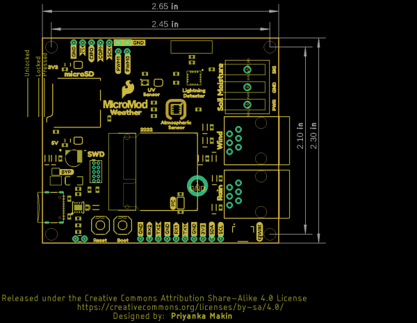
The Weather Carrier Board measures 2.65" x 2.30" (67.31mm x 58.42mm) and has four mounting holes that fit a standard 4-40 screw.
Hardware Assembly
Now that we are familiar with the hardware and sensors on the Weather Carrier Board, it's time to assemble it with your chosen MicroMod Processor and get it connected to your computer.
Inserting your Processor
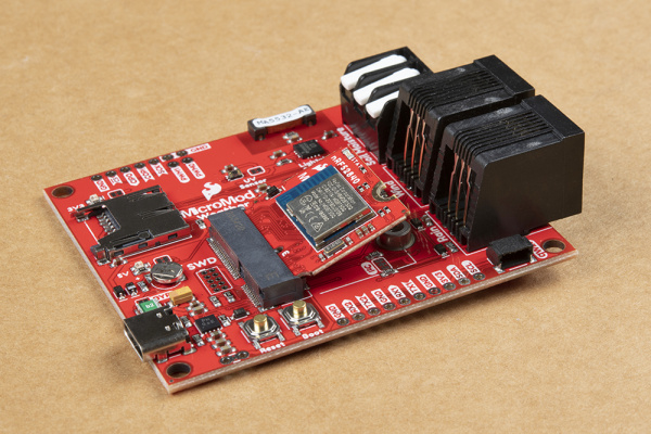
With the M.2 MicroMod connector, connecting your processor board is a breeze. Simply match up the key on your processor's beveled edge connector to the key on the M.2 connector. At a 45° angle, insert the processor board to the M.2 connector. The processor board will stick up at an angle as seen here:
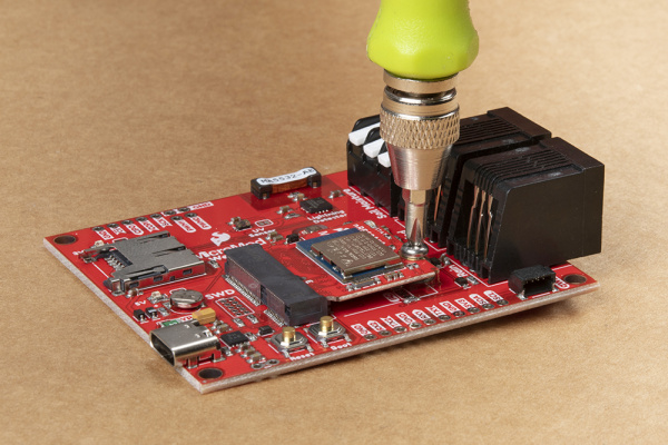
Once the board is in the socket, gently press the processor board down, grab the set screw and tighten it with a Phillip's head screwdriver:
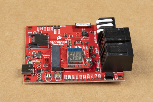
Once the processor board is secure, your assembled MicroMod system should look similar to the image below!
Assembling External Sensors
For users with the Soil Moisture Sensor and/or the Weather Meters Kit some extra assembly is required. We have detailed assembly instructions for both of these peripherals in their respective Hookup Guides. You can find them here:
Soil Moisture Sensor Hookup Guide
Weather Meter Hookup Guide
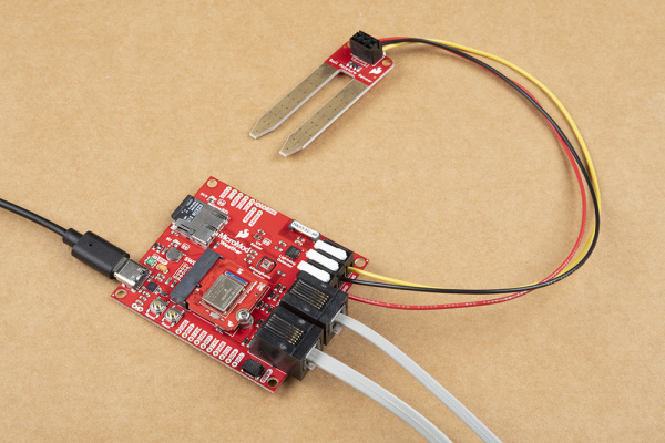
Once your external sensors are assembled, connecting them is a snap (literally). To connect the Soil Moisture Sensor, simply plug in the three wires to the three-pin latch terminals taking care to match the signals. For the Weather Meters, just plug the connectors for the Wind & Rain signals into their matching RJ11 jacks on the Weather Carrier Board.
Connecting Everything Up
With your processor inserted and secured it's time to connect your MicroMod Weather Carrier Board to your computer using the USB-C connector. Depending on which processor you choose and which drivers you already have installed, you may need to install drivers for your board. Refer to your processor's hookup guide for detailed instructions on how to install them.
With your MicroMod Weather Carrier Board, Processor Board, and any external sensors assembled we can now move on to uploading some code to monitor your environment! Head on to the next section for an example to test all the sensors the Weather Carrier Board features.
Weather Station Arduino Example
We've written a few examples to get started with the Weather Carrier Board. They can be found in the "Examples" folder of Hardware GitHub Repository and will work with any SparkFun MicroMod Processor you choose. In this section we'll only cover the comprehensive Weather Station example, but you can use the other examples to test each sensor on the Weather Carrier along with the additional soil moisture and weather meter sensors.
For this particular example, we are using the Artemis MicroMod Processor. Board definitions for this processor board can be found in the Software Setup and Programming section of the Artemis MicroMod Processor Board Hookup Guide.
If you are using a different processor, go to our MicroMod Processor Boards landing page, find your Processor, and head on over to its tutorial for help installing your board definition.
MicroMod Weather Carrier Board Test Example
Before getting started with the Weather Carrier Board Example you will need to install the Board Definitions for your chosen MicroMod Processor (outlined above) as well as the BME280, VEML6075 and AS3935 Arduino Libraries. You can install them using the Arduino Library manager and searching 'SparkFun BME280', 'SparkFun VEML6075' and 'SparkFun AS3935'. Alternatively, you can download the libraries from their respective GitHub repositories linked above or you can download the .ZIP for each of them by clicking the buttons below:
With the libraries and processor board definitions installed we can go ahead and move on to opening the MicroMod Weather Example sketch and uploading it to our MicroMod Processor. You can open a new blank sketch and copy the code from below or you can download the entire GitHub repository for the Weather Carrier Board which includes all of the examples by clicking the button below:
Navigate to the location the repository downloaded to and open the Examples folder. In that folder you'll find examples for each sensor as well as MM_Weather_CB_Test. Open that example in the Arduino IDE or copy the code below into a blank sketch, select your Board and Port and click "Upload".
language:c
/*
 * MicroMod Weather Carrier Board Example
 *
 * This sketch tests all of the weather sensors on the carrier board:
 * atmospheric sensor - BME280, UV sensor - VEML6075, lightning detector - AS3935,
 * soil moisture sensor, wind and rain meters.
 *
 * Priyanka Makin @ SparkX Labs
 * Original Creation Date: August 20, 2020
 *
 * This code is Lemonadeware; if you see me (or any other SparkFun employee) at the
 * local, and you've found our code helpful, please buy us a round!
 *
 * Hardware Connections:
 * Insert MicroMod Processor Board of your choice into the M.2 connector of the SparkFun Weather carrier
 *  Screw into place
 * Connect Weather carrier board to power useing USB-C cable
 * Connect SparkFun Soil Moisture Sensor to Weather carrier using latching terminals
 * Connect both wind and rain meters to Weather carrier using the RJ11 connectors
 */

#include <Wire.h>
#include <SPI.h>
#include "SparkFunBME280.h"
#include <SparkFun_VEML6075_Arduino_Library.h>
#include "SparkFun_AS3935.h"

BME280 tempSensor;
VEML6075 uv;
SparkFun_AS3935 lightning;

#define INDOOR 0x12
#define OUTDOOR 0xE
#define LIGHTNING_INT 0x08
#define DISTURBER_INT 0x04
#define NOISE_INT 0x01

#if defined(ESP_PLATFORM)
int LED_BUILTIN = 5;
//int A0 = 34;
int G0 = 4;
int D0 = 23;
//int A1 = 35;
int D1 = 27;
const int G3 = 17;
int G1 = 12;
#elif defined(ARDUINO_ARCH_SAMD)
int G0 = 2;
int D0 = 0;
int D1 = 1;
//const int lightningInt = G3;  //SPI does not currently work on the SAMD51 proto
//int spiCS = G1;
#endif

int soilPin = A0;  //Pin number that measures analog moisture signal
int soilPower = G0;  //Pin number that will power the soil moisture sensor
int WSPEED = D0; //Digital I/O pin for wind speed
int WDIR = A1; //Analog pin for wind direction
int RAIN = D1;   //Digital I/O pin for rain fall
const int lightningInt = G3; // Interrupt pin for lightning detection
int spiCS = G1; //SPI chip select pin

volatile bool rainFlag = false;
volatile bool windFlag = false;

//Function is called every time the rain bucket tips
void rainIRQ()
{
  rainFlag = true;
}

//Function is called when the magnet in the anemometer is activated
void wspeedIRQ()
{
  windFlag = true;
}

// This variable holds the number representing the lightning or non-lightning
// event issued by the lightning detector.
int intVal = 0;
int noise = 2; // Value between 1-7
int disturber = 2; // Value between 1-10

void setup() {
  Serial.begin(115200);
  while (!Serial);

  Serial.println("MicroMod Weather Carrier Board Test");
  Serial.println();

  Wire.begin();
  SPI.begin();

  if (tempSensor.beginI2C() == false) { //Begin communication over I2C
    Serial.println("BME280 did not respond.");
    while(1); //Freeze
  }
  if (uv.begin() == false) {
    Serial.println("VEML6075 did not respond.");
    while(1);
  }

  pinMode(LED_BUILTIN, OUTPUT);
  pinMode(soilPower, OUTPUT);
  digitalWrite(soilPower, LOW);
  // When lightning is detected the interrupt pin goes HIGH.
  pinMode(lightningInt, INPUT);

  //Initialization for weather meter
  pinMode(WSPEED, INPUT_PULLUP);  //Input from wind meters windspeed sensor
  pinMode(RAIN, INPUT_PULLUP);    //Input from wind meters rain gauge sensor
  //attach external interrupt pins to IRQ functions
  attachInterrupt(digitalPinToInterrupt(RAIN), rainIRQ, FALLING);
  attachInterrupt(digitalPinToInterrupt(WSPEED), wspeedIRQ, FALLING);
  //turn on interrupts
  interrupts();

  if(lightning.beginSPI(spiCS, 2000000) == false){
    Serial.println ("Lightning Detector did not start up, freezing!");
    while(1);
  }
  else
    Serial.println("Schmow-ZoW, Lightning Detector Ready!");

  // The lightning detector defaults to an indoor setting at
  // the cost of less sensitivity, if you plan on using this outdoors
  // uncomment the following line:
  lightning.setIndoorOutdoor(OUTDOOR);
}

// the loop function runs over and over again forever
void loop() {
  digitalWrite(LED_BUILTIN, HIGH);   // turn the LED on (HIGH is the voltage level)

  Serial.println();
  Serial.print("Temperature: ");
  Serial.println(tempSensor.readTempF(), 2);
  Serial.print("Humidity: ");
  Serial.println(tempSensor.readFloatHumidity(), 0);
  Serial.print("Pressure: ");
  Serial.println(tempSensor.readFloatPressure(), 0);
  Serial.print("Altitude: ");
  Serial.println(tempSensor.readFloatAltitudeFeet(), 1);

  Serial.print("UV A, B, index: ");
  Serial.println(String(uv.uva()) + ", " + String(uv.uvb()) + ", "+ String(uv.index()));

  Serial.print("Soil Moisture = ");
  Serial.println(readSoil());

  Serial.print("Wind direction: ");
  Serial.print(getWindDirection());
  Serial.println(" degrees");
  //Check interrupt flags
  if (rainFlag == true){
    Serial.println("Rain click!");
    rainFlag = false;
  }
  if (windFlag == true){
    Serial.println("Wind click!");
    windFlag = false;
  }

  // Hardware has alerted us to an event, now we read the interrupt register
  if(digitalRead(lightningInt) == HIGH){
    intVal = lightning.readInterruptReg();
    if(intVal == NOISE_INT){
      Serial.println("Noise.");
      // Too much noise? Uncomment the code below, a higher number means better
      // noise rejection.
      //lightning.setNoiseLevel(noise);
    }
    else if(intVal == DISTURBER_INT){
      Serial.println("Disturber.");
      // Too many disturbers? Uncomment the code below, a higher number means better
      // disturber rejection.
      //lightning.watchdogThreshold(disturber);
    }
    else if(intVal == LIGHTNING_INT){
      Serial.println("Lightning Strike Detected!");
      // Lightning! Now how far away is it? Distance estimation takes into
      // account any previously seen events in the last 15 seconds.
      byte distance = lightning.distanceToStorm();
      Serial.print("Approximately: ");
      Serial.print(distance);
      Serial.println("km away!");
    }
  }

  digitalWrite(LED_BUILTIN, LOW);    // turn the LED off by making the voltage LOW

  delay(3000);
}

int readSoil() {
  int moistVal = 0;  //Variable for storing moisture value
  //Power Senor
  digitalWrite(soilPower, HIGH);
  delay(10);
  moistVal = analogRead(soilPin);  //Read the SIG value from sensor
  digitalWrite(soilPower, LOW); //Turn the sensor off
  return moistVal; //Return current moisture value
}

int getWindDirection()
{
  unsigned int adc;
  adc = analogRead(WDIR); //get the current readings from the sensor

  if (adc < 380) return (113);
  if (adc < 393) return (68);
  if (adc < 414) return (90);
  if (adc < 456) return (158);
  if (adc < 508) return (135);
  if (adc < 551) return (203);
  if (adc < 615) return (180);
  if (adc < 680) return (23);
  if (adc < 746) return (45);
  if (adc < 801) return (248);
  if (adc < 833) return (225);
  if (adc < 878) return (338);
  if (adc < 913) return (0);
  if (adc < 940) return (293);
  if (adc < 967) return (315);
  if (adc < 990) return (270);
  return (-1);
}
The code begins by checking which MicroMod Processor was selected in Arduino and adjusts a few pin settings accordingly so it will work with any SparkFun MicroMod Processor. Next, it initializes all the on board sensors and checks for proper responses as well as checking for external sensors (wind, rain and soil).
Once all the sensors initialize, the code prints out data from each sensor. Open your serial monitor and set the baud to 115200 to watch the data print out.
Resources and Going Further
For more information about the MicroMod Weather Carrier Board, check out the following links:
- Eagle Files (ZIP)
- Schematic (PDF)
- Dimensional Drawing (PNG)
- GitHub Hardware Repository
- BME280 Arduino Library
- BME280 Datasheet (PDF)
- VEML6075 Arduino Library
- VEML6075 Datasheet (PDF)
- AS3935 Arduino Library
- AS3935 Datasheet (PDF)
For more information about the SparkFun MicroMod Ecosystem, take a look at the links below:
Looking for some project inspiration using your Weather Station Carrier? The tutorials below can help you get started!
