MicroMod Single Pair Ethernet Function Board - ADIN1110 Hookup Guide
 QCPete,
  El Duderino
Hardware Assembly
If you're not familiar with assembling boards using the MicroMod connection system, head over to the MicroMod Main Board Hookup Guide for information on inserting and securing your MicroMod Processor and Function Boards to the Main Board:
MicroMod Main Board Hookup Guide
Single Pair Ethernet Basic Assembly
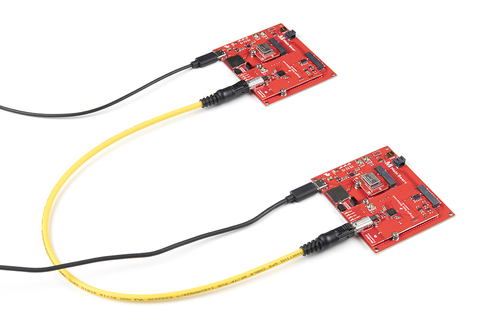
With the Function and Processor Boards connected to their respective Main Boards, we can complete the assembly of the Single Pair Ethernet circuit. For a basic SPE prototyping circuit either with your own setup or with the Single Pair Ethernet Kit, connect the two MicroMod assemblies together using a Single Pair Ethernet Cable and then power the two MicroMod Main Boards via USB-C like the photo below:
Demo Circuit Assembly
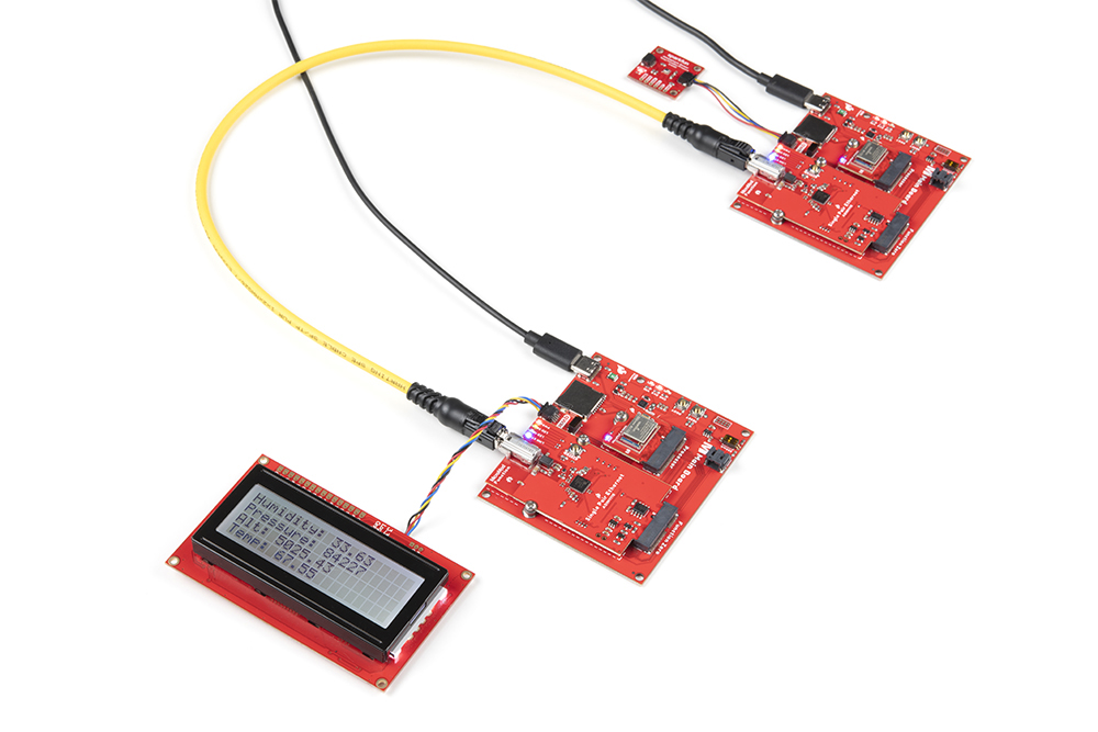
We'll be assembling a demo circuit that works with an example pair included in the ADIN1110 Arduino Library that sends environmental data recorded by the SparkFun Atmospheric Sensor Breakout - BME280 (Qwiic) connected to one SPE MicroMod assembly to display on a SparkFun 20x4 SerLCD - RGB Backlight (Qwiic) connected to the opposite SPE MicroMod assembly.
Connect the Qwiic boards to the Qwiic connector on their respective MicroMod Main Boards then plug the SPE cable into the T1 jacks on each Function Board. Once all of those are connected, power the MicroMod Main boards with USB-C cables. The completed demo circuit should look like the photo below:
Now that our demo circuit is complete, we can move on to uploading the code to establish a SPE link and send data between the two MicroMod assemblies.