MicroMod Alorium Sno M2 Processor Board Hookup Guide
Hardware Overview
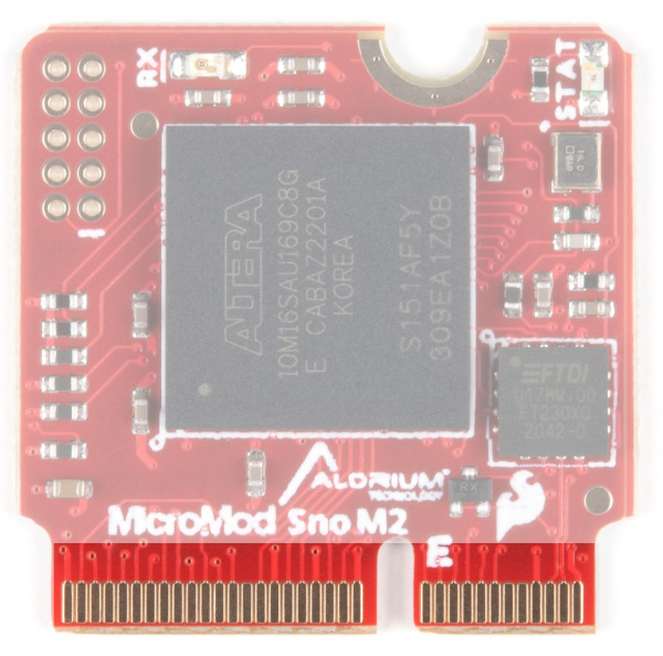
M.2 Connector
All of our MicroMod Processor Boards come equipped with the M.2 MicroMod Connector, which leverages the M.2 standard and specification to allow you to install your MicroMod Processor Board on your choice of carrier board. Most of the pins use a common pinout to ensure cross platform compatibility.
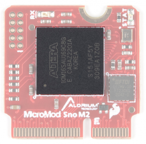
Alorium Technology Sno M2 Processor
The Alorium Technology Sno FPGA provides a reconfigurable hardware platform that hosts an ATmega328 instruction set compatible microcontroller. The FPGA also provides the ability to implement custom logic that accelerates specific functionality that is slow, problematic or even impossible for an 8-bit microcontroller.
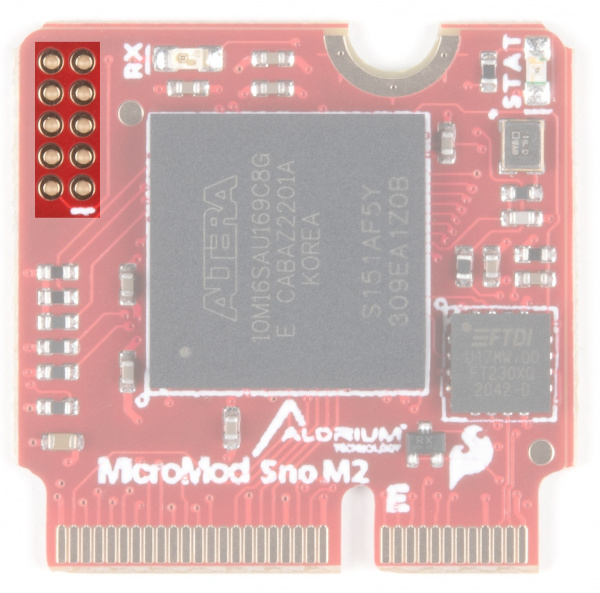
JTAG
The JTAG interface on Sno M2 is primarily used during manufacturing to load the production FPGA image. For advanced users, JTAG can be used for creating bare-metal FPGA designs and directly flashing a new image to the FPGA.
The Sno M2 FPGA has been designed to be modified and extended by using Alorium’s OpenXLR8 Methodology. This flow provides a path to create custom XBs in the FPGA fabric that can easily interface to the on-chip microcontroller and preserve full factory functionality.
Learn More about OpenXLR8 here.
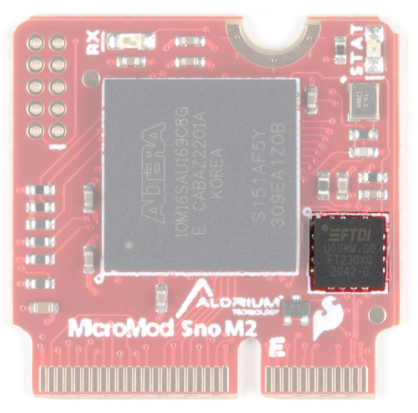
FTDI
The FTDI facilitates USB communication - drivers for the FTDI chip may need to be installed. Please see the How to Install FTDI drivers tutorial if you need help installing these drivers.
LEDs
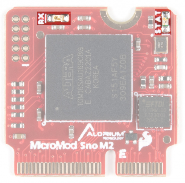
There are two LEDs on the Sno Processor Board. An RX LED and a STAT LED.
RX LED - The RX LED indicates activity on the USB serial port.
STAT LED - A STAT LED is added to the top side of the board. This is useful debugging or as a status indicator.
MicroMod Alorium Sno M2 Processor Pin Functionality
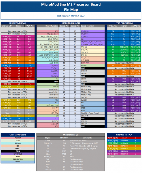
The complete pin map is shown here or you can refer to the schematic. You can also download the PDF version of the pin map here.
Board Dimensions
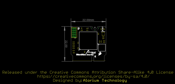
The board takes advantage of the standard MicroMod form factor.
