LSM9DS1 Breakout Hookup Guide
 jimblom
Hardware Assembly
On this page we'll discuss assembly hints. There's really not much to assembling the breakout board -- the real key is soldering something into the breakout holes.
Solder Something
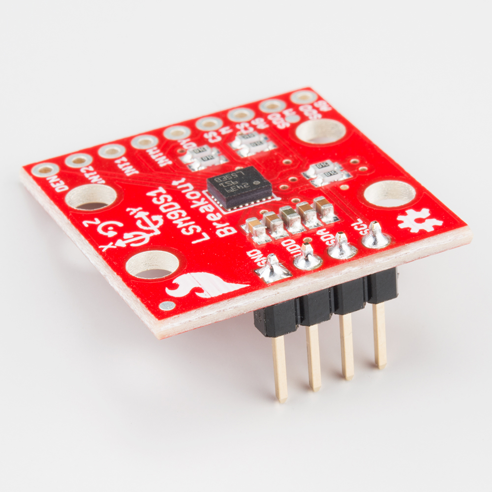
To get a solid electrical and physical connection to the LSM9DS1 Breakout, you'll need to solder either connectors or wires to the break-out pins. What, exactly, you solder into the board depends on how you're going to use it.
If you're going to use the breakout board in a breadboard or similar 0.1"-spaced perfboard, we recommend soldering straight male headers into the pins (there are also long headers if you need 'em).
If you're only going to use the I2C interface -- and ignore the interrupts -- you can get away with soldering just the four-pin header.
If you're going to mount the breakout into a tight place, you may want to opt for soldering wires (stranded or solid-core) into the pins.
Mounting the Breakout
Because the LSM9DS1 senses motion, it's important (for most applications, at least) to keep it pinned in place. So the boards have four mounting holes toward the corners. The drill holes are 0.13" in diameter, so they should accommodate any 4/40 screw.
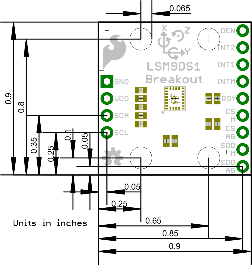
Consult the EAGLE PCB design files to find out more about the Breakout's dimensions.