Live Spotify Album Art Display
This Tutorial is Retired!
This tutorial covers concepts or technologies that are no longer current. It's still here for you to read and enjoy, but may not be as useful as our newest tutorials.
 Englandsaurus
Hardware Assembly
I usually solder some female headers to my ESP32 for ease of connection. If you're making a permanent fixture, it's probably a good idea to solder the connections straight into your ESP32 or make a custom shield. If you have not already, solder the headers or wires of your choice to your ESP32.
Hookup Table
There should be two ports on the back of your matrix, one on the left (input) and one on the right (output). We'll refer to the port on the left as PI while the right as PO.
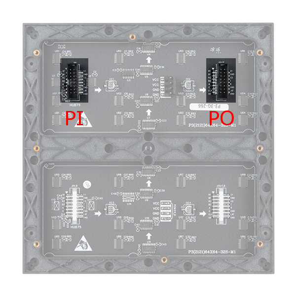
You'll have some connections between the input port and the output port. You'll have some connections between your ESP32 to the input port. Let's start with the connections between the two ports. Insert the 16-pin (2x8) ribbon cable into the PI port. Then using the M/F jumper wires between the following pins.
| Input Panel Pin Label (PI) | Output Panel Pin Label (PO) |
|---|---|
| R2 | R1 |
| G1 | R2 |
| G2 | G1 |
| B1 | G2 |
| B2 | B1 |
You'll then need to connect much of your color data to the output port. Finish the connection between your PI port and the ESP32 using the following table using M/M jumper wires.
| Input Panel Pin Label (PI) | ESP32 Pins |
|---|---|
| STB/LAT | 22 |
| A | 19 |
| B | 23 |
| C | 18 |
| D | 5 |
| E | 15 |
| OE | 2 |
| CLK | 14 |
| R1 | 13 |
| GND | GND |
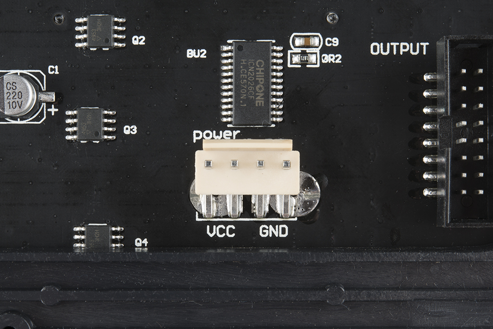
Power Connector
At this point, you can go ahead and connect your selected power supply to 5V and ground on the back of the display using the 4-pin polarized cable and barrel jack adapter. If you are powering the panel with a separate power supply, make sure to connect ground for reference. If you are powering the panel and ESP32 off a single power supply, make sure you add a 5V line going to either of your ESP32's VUSB pins.