LilyPad USB Plus Hookup Guide
 Gella
Gella 
Technical Notes
If you are already familiar with programming Arduino for a while, read on for some additional notes about the LilyPad USB Plus. It's similar to other Arduinos, but has some special features and limitations you'll want to know about.
Using a Battery and Battery Charging
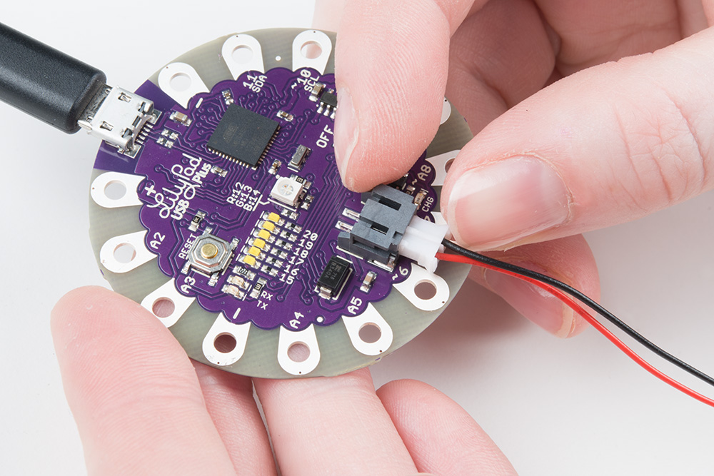
SparkFun sells a number of LiPo batteries compatible with this board. If you are new to the LilyPad system, we recommend the E-Textiles Battery. If you're supplying your own battery, use a single-cell (3.7V) LiPo battery with a JST connector.
Batteries with larger capacities (measured as amp-hours or Ah) will run the board longer before needing recharging. How long will depend on how many LEDs your program turns on, etc. If you're just running a few LEDs, you can expect the board to run about 5 hours for every 100mAh of battery capacity.
Charge Rate
To recharge an attached battery, plug the board into a USB power source.
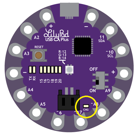
While the battery is charging, the "CHG" LED will illuminate. When the battery is fully charged the LED will turn off. The default charge current is set to 100mA, so a 100mAh battery will recharge in one hour, a 1000mAh battery in 10 hours, etc. Since the board is set to charge at a rate of 100mA, we do not recommend connecting a lower capacity LiPo battery (i.e. 40mAh LiPo battery) to charge.
It is safe to leave a LiPo battery attached to the board permanently, even with USB power applied. The battery will not be overcharged.
Notes on Washing LilyPad Projects
Removing the LiPo Battery
The battery connector can be tight; to remove a battery never pull on the wires. Use a pair of needle nose pliers or cutters to gently hold pull the plug out of the connector.

Pin Numbering
Below is a list of the LilyPad USB Plus I/O pins and each function.
Legend:
- n = digital pin
- ~n = PWM-capable pin
- An = analog-capable pin
- (n) = internal pin (not connected to sew tab)
- [n] = internal pin (available on an exposed via)
| Function | Digital | Analog |
|---|---|---|
| RX_LED | (0) | |
| RX_LED/SS | (1) | |
| 2 | A2 | |
| 3 | A3 | |
| 4 | A4 | |
| 5 | A5 | |
| ~6 | ||
| ~7 | A7 | |
| ~8 | A8 | |
| 9 | A9 | |
| SCL | ~10 | |
| SDA | 11 | |
| RGB LED - Red | (~12) | |
| RGB LED - Green | (~13) | |
| RGB LED - Blue | (~14) | |
| Bar Graph LED 0 | (15) | |
| Bar Graph LED 1 | (16) | |
| Bar Graph LED 2 | (17) | |
| Bar Graph LED 3 | (18) | |
| Bar Graph LED 4 | (19) | |
| Bar Graph LED 5 | (20) | |
| SCLK | [21] | |
| MOSI | [22] | |
| MISO | [23] |