LIDAR-Lite v3 Hookup Guide
 Shawn Hymel
 Introduction
The LIDAR-Lite Series - the v3 and v3HP - are compact optical distance measurement sensors, which are ideal for drones and unmanned vehicles.
LIDAR is a combination of the words "light" and "RADAR." Or, if you'd like, a backronym for "LIght Detection and Ranging" or "Laser Imaging, Detection, and Ranging." At it's core, LIDAR works by shooting a laser at an object and then measuring the time it takes for that light to return to the sensor. With this, the distance to the object can be measured with fairly good accuracy.
By sweeping or spinning a LIDAR unit, systems can create detailed distance maps. Survey equipment, satellites, and aircraft can be equipped with complex LIDAR systems to create topographic maps of terrain and buildings. Luckily, Garmin™ has created a user-friendly LIDAR unit for your robotics and DIY needs!
Note that these use a Class 1 Laser, if you are concerned about your safety (in short: A Class 1 laser is safe under all conditions of normal use).
Suggested Viewing
What is the difference between the LIDAR-Lite v3 and the LIDAR-Lite v3HP? Let's ask Shawn Hymel!
Required Materials
To follow along with this project tutorial, you will need the following materials:
Suggested Reading
If you aren't familiar with the following concepts, we recommend checking out these tutorials before continuing.
Installing an Arduino Library
How to Use a Breadboard
What is an Arduino?
Installing Arduino IDE
I2C
Hardware Overview
Differences Between v3 and v3HP
Functionally, the LIDAR-Lite v3 and LIDAR-Lite v3HP are quite similar. The primary differences are listed here:
| Specs | LIDAR-Lite v3 | LIDAR-Lite v3HP |
|---|---|---|
| Update Rate | 500 Hz | > 1kHz |
| Current Consumption (idle) | 105 mA | 65 mA |
| Current Consumption (acquisition) | 130 mA | 85 mA |
| Casing | None | IPX7 rated casing |
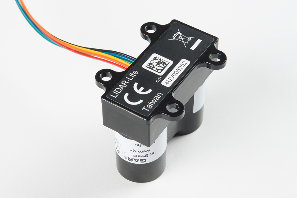
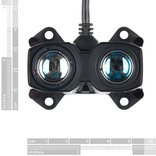
Case
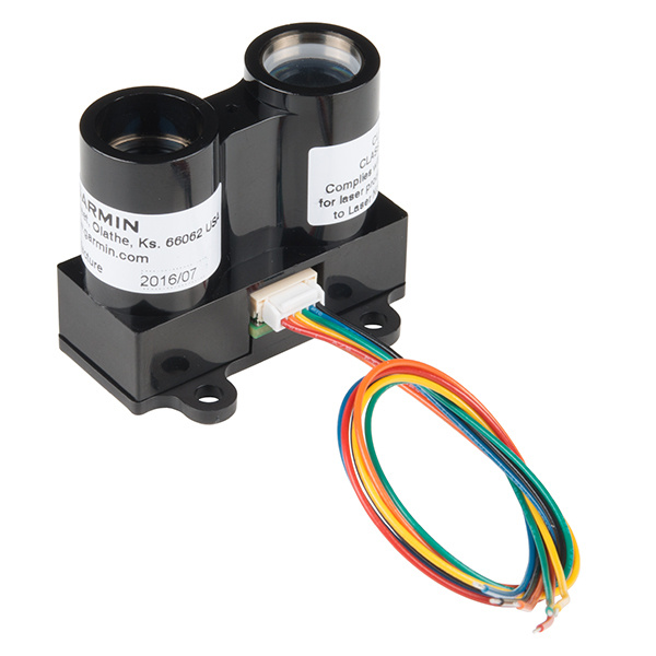
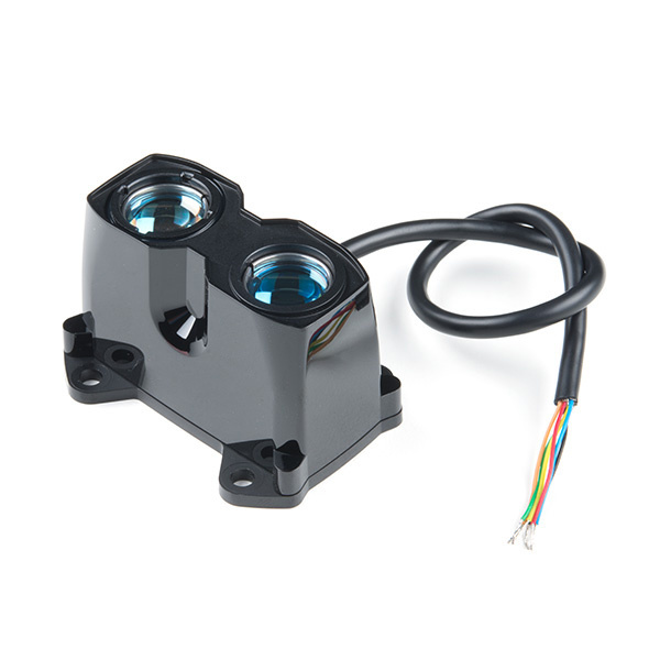
The LIDAR-Lite has two tubes on the front that contain a transmitter (laser) and receiver. You'll want to face these toward your target.
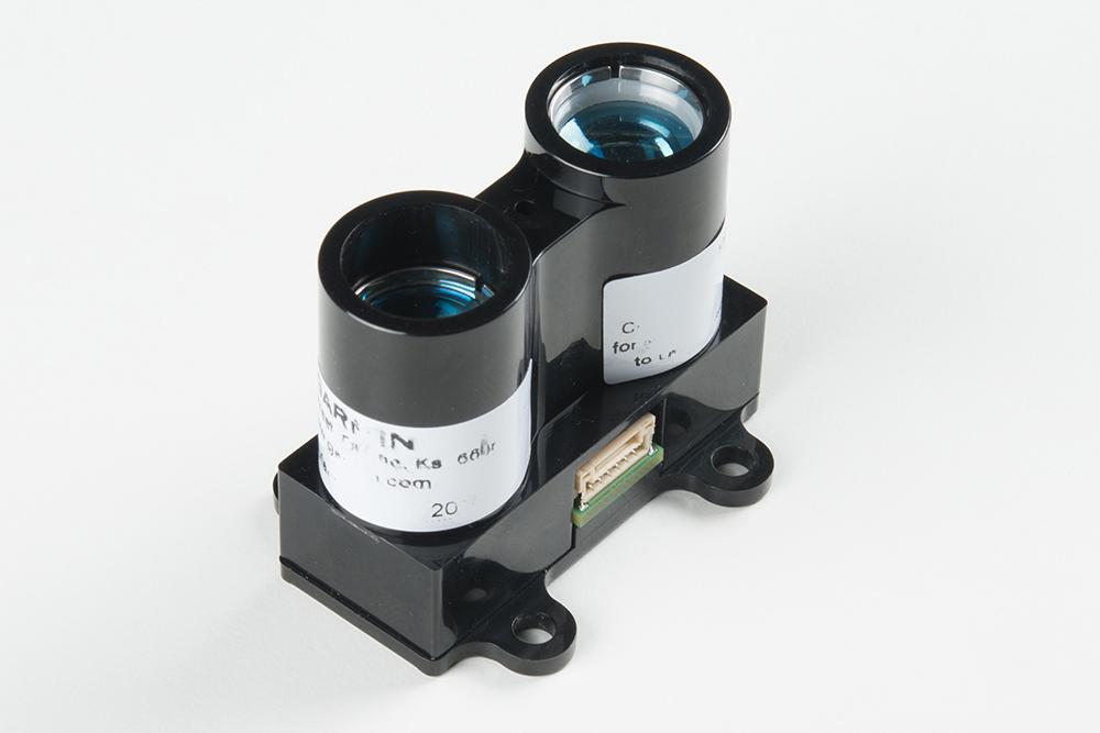
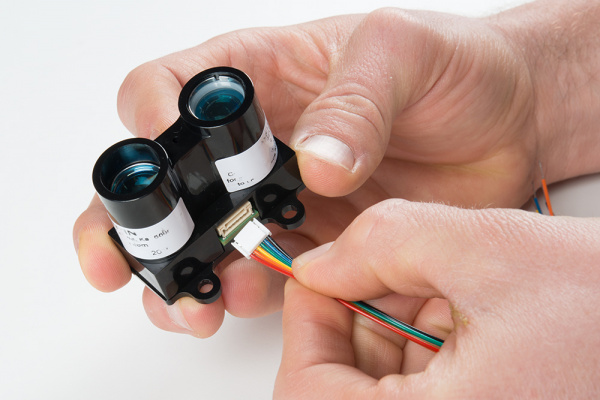
On the side, you'll find an electrical port that connects to the included 6-wire cable. Plug in the wire harness to the port to break out the pins.
On the back, you'll find 4 mounting holes that are designed to accept #6 or M3.5 screws or bolts.
Wires
The LIDAR-Lite has 6 wires that can be used to communicate with the sensor.
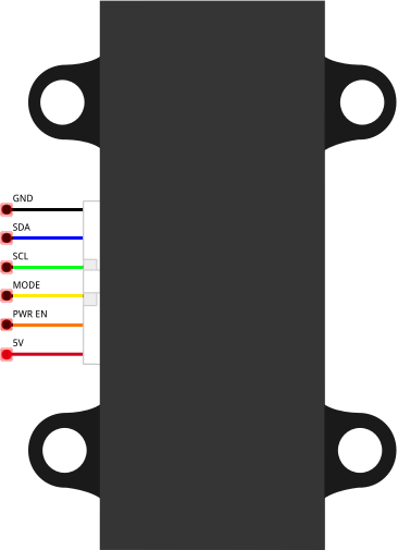
| Color | Pin | Description |
|---|---|---|
| Red | 5V | Power (5V) |
| Orange | PWR EN | Power enable (internal pullup) |
| Yellow | MODE | Mode control (for PWM mode) |
| Green | SCL | I2C clock |
| Blue | SDA | I2C data |
| Black | GND | Ground |
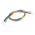
LIDAR-Lite Accessory Cable
CAB-14043Power
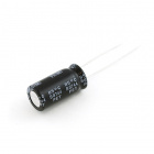
Both the LIDAR-Lite v3 as well as the LIDAR-Lite v3HP units require between 4.5V to 5.5V of DC power to operate (nominally, 5V). The LIDAR-LITE v3 can draw up to 135 mA of current during continuous operation (105 mA at idle). Contrarily, the v3HP unit draws up to 85 mA of current during continuous operation (65 mA at idle). To maintain a level voltage, Garmin recommends putting a 680 μF capacitor between power (5V) and ground (GND) as close to the LIDAR unit as possible.
Hardware Assembly
Follow the diagram below to connect the LIDAR unit to a RedBoard or other Arduino-compatible board. The LIDAR-Lite can communicate over I2C as well as use a pulse-width modulated (PWM) signal to denote measured distances. For this guide, we will show how to use I2C to communicate with the LIDAR unit.
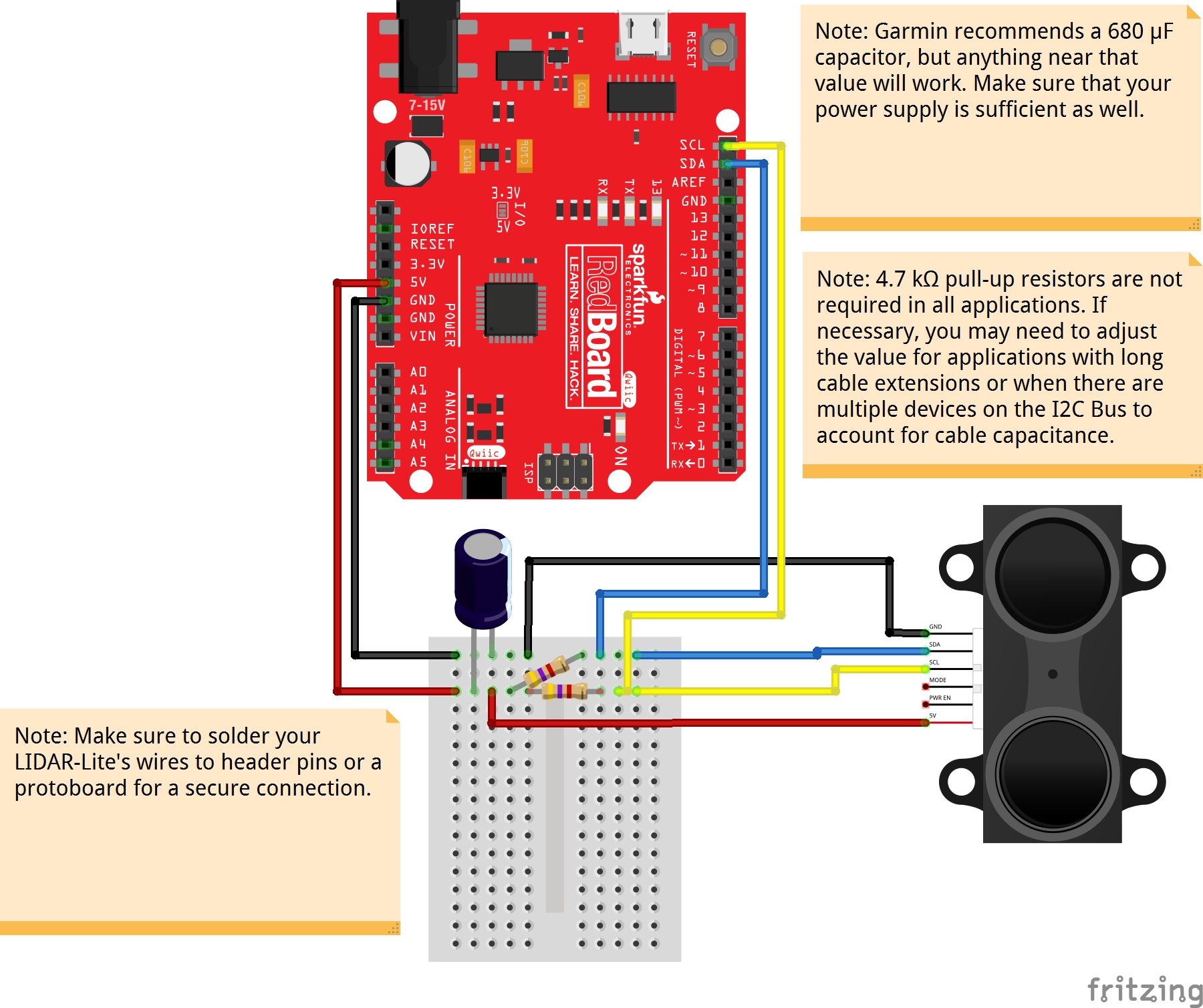
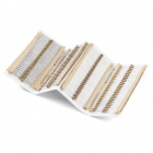
You also may need I2C pull-up resistors for the SCL and SDA lines. It depends on the length between the Arduino and I2C device but usually a 4.7kΩ resistor is a good start. For long runs or systems with lots of devices, it is recommended to use smaller resistors. You can also use a I2C bus extender for distances beyond the maximum bus length as well.
Software
Note: This example assumes you are using the latest version of the Arduino IDE on your desktop. If this is your first time using Arduino, please review our tutorial on installing the Arduino IDE. If you have not previously installed an Arduino library, please check out our installation guide.
Garmin maintains an Arduino library to make working with the LIDAR-Lite very easy. Visit the GitHub repository, or click the button below to download the library.
Open a new Arduino sketch, and copy in the following code:
language:c
/**
 * LIDARLite I2C Example
 * Author: Garmin
 * Modified by: Shawn Hymel (SparkFun Electronics)
 * Date: June 29, 2017
 *
 * Read distance from LIDAR-Lite v3 over I2C
 *
 * See the Operation Manual for wiring diagrams and more information:
 * http://static.garmin.com/pumac/LIDAR_Lite_v3_Operation_Manual_and_Technical_Specifications.pdf
 */

#include <Wire.h>
#include <LIDARLite.h>

// Globals
LIDARLite lidarLite;
int cal_cnt = 0;

void setup()
{
  Serial.begin(9600); // Initialize serial connection to display distance readings

  lidarLite.begin(0, true); // Set configuration to default and I2C to 400 kHz
  lidarLite.configure(0); // Change this number to try out alternate configurations
}

void loop()
{
  int dist;

  // At the beginning of every 100 readings,
  // take a measurement with receiver bias correction
  if ( cal_cnt == 0 ) {
    dist = lidarLite.distance();      // With bias correction
  } else {
    dist = lidarLite.distance(false); // Without bias correction
  }

  // Increment reading counter
  cal_cnt++;
  cal_cnt = cal_cnt % 100;

  // Display distance
  Serial.print(dist);
  Serial.println(" cm");

  delay(10);
}
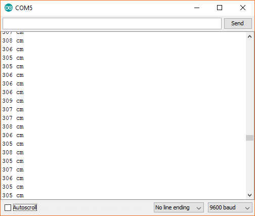
Upload the program, and open a Serial Monitor. You should see distance measurements (in cm) being printed.
Troubleshooting
Arduino Output Error Poor Connection
Are you seeing this output from the LIDAR-Lite V3 I2C example code with the decoupling capacitors connected to the Arduino?
> nack
> nack
> nack
You probably do not have a secure connection between the Lidar and the Arduino. I2C is sensitive to its connection. The cable wires are thin and can disconnect when in the Arduino's female header from a bump. A breadboard seems to work fine if there is not a lot of mechanical vibrations. However, a small bump can mess up the timing for the I2C even on the breadboard.
 |
 |
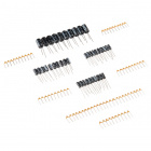
For a secure connection, it is recommended soldering header pins with some heat shrink or make sort of adapter when connecting it to an Arduino. Once disconnected, the Arduino might stop outputting sensor data. You can reset the Arduino for testing but to prevent the wires from disconnecting, it would be better to solder the wires to header pins. This is a common "issue" with any I2C sensor and if they do not secure the wires, the Arduino will have problems talking with the Lidar Lite V3.


Arduino Output Error I2C Pull-Up Resistors
Another reason for the nack error may be that you need I2C pull-up resistors for the SCL and SDA lines. It depends on the length between the Arduino and I2C device but usually a 4.7kΩ resistor is a good start. For long runs or systems with lots of devices, it is recommended to use smaller resistors. You can also use a I2C bus extender for distances beyond the maximum bus length as well.
Decoupling Capacitor
Looking for a 680µF capacitor? Unfortunately, the SparkFun catalog does not include a 680µF capacitor. There are 1000µF capacitors, which can work as a substitute with the Lidar Lite.
Or, you can also wire capacitors in series and parallel to get an equivalent capacitance.
 |
Dimensions
For more details on the dimensions, check out the links below.
Product Showcase Example for LIDAR-Lite V3 Wand
Looking for the example code used in the product video for the LIDAR-LIte V3? Nick Poole basically used the same parts and example code that was used with the Lidar Lite V2 Glasses. For the Lidar Lite V3 Wand, he used the following components:
- LEDs
- micro-B USB breakout
- micro-B USB Cable
- a backup portable cell phone charger
- 1kΩ resistor
- 5V/16 MHz Pro Micro
He happened to have a 5V/16 MHz Pro Micro around when building the project for the Lidar Lite V2 Glasses. The parts were reused for the Lidar Lite V3 Wand. Try looking at the old wishlist for the Lidar Lite V2 Glasses for more information. Make sure to also add a 1kΩ resistor when using the PWM wiring as stated on page 3 of the user manual.
Additional Troubleshooting
Looking for additional troubleshooting tips and application notes related to the LIDAR Lite? Check out Garmin's support on the LIDAR Lite:
Application Notes on Reflective Surfaces
For more application notes on using the LIDAR-Lite v3/v3HP, check out the link below.
This can also be found in the operation & technical manual on page 11.
Resources and Going Further
Now that you've successfully got your LIDAR up and running, it's time to incorporate it into your own project!
For more information, check out the resources below:
- Operation & Technical Manual
- Garmin's Product Page
- SparkFun Product Showcase
- LIDAR-Lite Module Demo
- GitHub Repo - LIDAR-Lite Glasses - Example Code used for the LIDAR-Lite Glasses and Lidar LIte V3 Wand
- SparkFun Speed Trap
- LIDAR-Lite V3 Demo
- LIDAR-Lite v3HP
- GitHub Repository
- Fritzing Diagram - The old Fritzing Part can be found from this repository. The pinout is the same so it can be used to represent the LIDAR-Lite V3.
- LIDAR-Lite V3/v3HP Arduino Library
- LIDAR-Lite Module Demo
Want to know more about how LIDAR works? Check out this great YouTube video:
Need some inspiration for your next project? Check out some of these related tutorials:
Large Digit Driver Hookup Guide
ReconBot with the Tessel 2
Building an Autonomous Vehicle: The Batmobile
Or check out these 3D Scanner projects using the LIDAR-Lite V3.
https://youtu.be/rK1msOx21Ls
Or check out these related blog post.