I2C
I2C at the Hardware Level
Signals
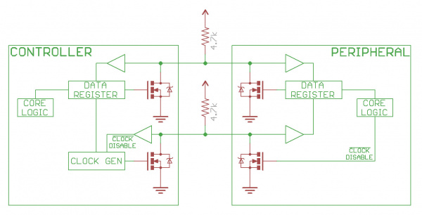
Each I2C bus consists of two signals: SDA and SCL. SDA (Serial Data) is the data signal and SCL (Serial Clock) is the clock signal. The clock signal is always generated by the current bus controller; some peripheral devices may force the clock low at times to delay the controller sending more data (or to require more time to prepare data before the controller attempts to clock it out). This is called "clock stretching" and is described on the protocol page.
Unlike UART or SPI connections, the I2C bus drivers are "open drain", meaning that they can pull the corresponding signal line low, but cannot drive it high. Thus, there can be no bus contention where one device is trying to drive the line high while another tries to pull it low, eliminating the potential for damage to the drivers or excessive power dissipation in the system. Each signal line has a pull-up resistor on it, to restore the signal to high when no device is asserting it low.
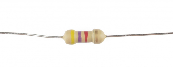
Resistor selection varies with devices on the bus, but a good rule of thumb is to start with 4.7kΩ resistor and adjust down if necessary. I2C is a fairly robust protocol, and can be used with short runs of wire (2-3m). For long runs, or systems with lots of devices, smaller resistors are better.
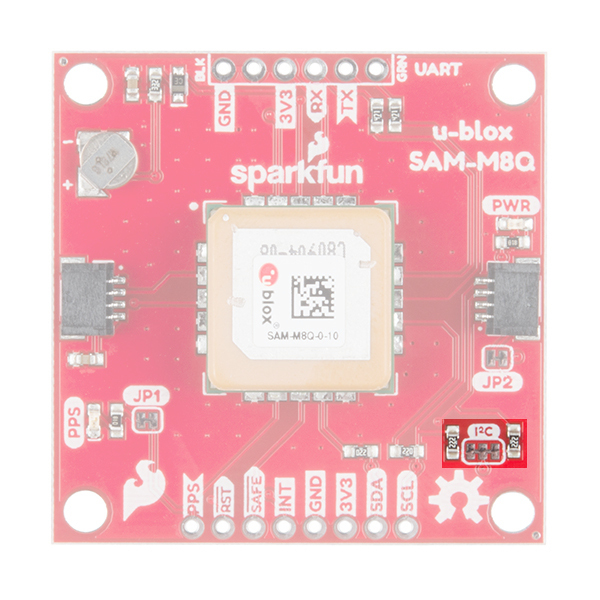
Most I2C devices offered in the SparkFun catalog usually include pull-up resistors for the SCL and SDA pins. If you have many I2C devices on the same bus, you may need to adjust the equivalent value for the pull-up resistors by disconnecting the pull-up resistors on a few of the devices. Depending on what is connected to the bus and the design, you can include about 7x I2C devices on the same bus. However, if you are having any issues, you can cut the two traces connecting to the center jumper pad using an hobby knife or remove solder on the three jumper pads using a soldering iron to disconnect the resistors on certain boards. As you can see, the design of the GPS board on the left used traces to connect the jumper pads for the pull-up resistors. The design of the GPS board on the right used solder to connect the jumper pads for the pull-up resistors.
 |
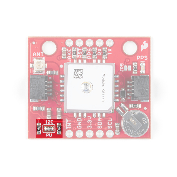 |
| Trace Connecting Jumper Pads on the SAM-M8Q | Solder Connecting Jumper Pads on the XA1110 |
If your design requires longer runs of wire, you can use a dedicated IC to extend the signal such as the PCA9615 in the following products.
SparkFun QwiicBus Hookup Guide
Qwiic Differential I2C Bus Extender (PCA9615) Hookup Guide
Signal Logic Levels
Since the devices on the bus don't actually drive the signals high, I2C allows for some flexibility in connecting devices with different I/O voltages. In general, in a system where one device is at a higher voltage than another, it may be possible to connect the two devices via I2C without any level shifting circuitry in between them. The trick is to connect the pull-up resistors to the lower of the two voltages. This only works in some cases, where the lower of the two system voltages exceeds the high-level input voltage of the the higher voltage system--for example, a 5V Arduino and a 3.3V accelerometer. Depending on the design of the Arduino or the I2C device, we recommend using a logic level converter to be consistent and avoid damaging any device on the bus.
If the voltage difference between the two systems is too great (say, 5V and 2.5V), SparkFun offers a simple I2C level shifter board — e.g. the PCA9306 Level Translator Breakout. This dedicated level shifter board the board also includes an enable line, it can be used to disable communications to selected devices. This is useful in cases where more than one device with the same address is to be connected to a single controller — Wii Nunchucks are a good example. There are also bi-directional logic level converters that can be used.
