I2C
 SFUptownMaker
 Protocol
Communication via I2C is more complex than with a UART or SPI solution. The signalling must adhere to a certain protocol for the devices on the bus to recognize it as valid I2C communications. Fortunately, most devices take care of all the fiddly details for you, allowing you to concentrate on the data you wish to exchange.
Basics
Messages are broken up into two types of frame: an address frame, where the controller indicates the peripheral to which the message is being sent, and one or more data frames, which are 8-bit data messages passed from controller to peripheral or vice versa. Data is placed on the SDA line after SCL goes low, and is sampled after the SCL line goes high. The time between clock edge and data read/write is defined by the devices on the bus and will vary from chip to chip.
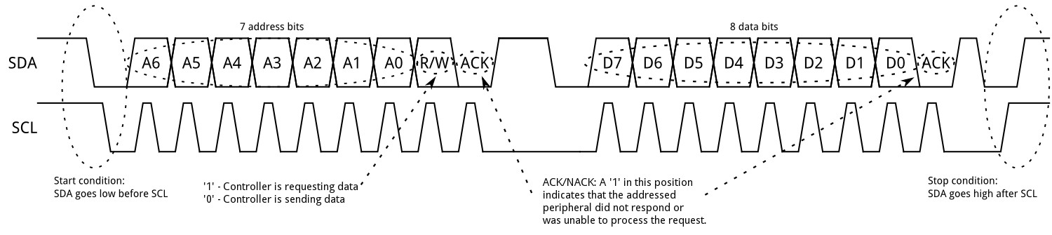
Start Condition
To initiate the address frame, the controller device leaves SCL high and pulls SDA low. This puts all peripheral devices on notice that a transmission is about to start. If two controllers wish to take ownership of the bus at one time, whichever device pulls SDA low first wins the race and gains control of the bus. It is possible to issue repeated starts, initiating a new communication sequence without relinquishing control of the bus to other controller(s); we'll talk about that later.
Address Frame
The address frame is always first in any new communication sequence. For a 7-bit address, the address is clocked out most significant bit (MSB) first, followed by a R/W bit indicating whether this is a read (1) or write (0) operation.
The 9th bit of the frame is the NACK/ACK bit. This is the case for all frames (data or address). Once the first 8 bits of the frame are sent, the receiving device is given control over SDA. If the receiving device does not pull the SDA line low before the 9th clock pulse, it can be inferred that the receiving device either did not receive the data or did not know how to parse the message. In that case, the exchange halts, and it's up to the controller of the system to decide how to proceed.
Data Frames
After the address frame has been sent, data can begin being transmitted. The controller will simply continue generating clock pulses at a regular interval, and the data will be placed on SDA by either the controller or the peripheral, depending on whether the R/W bit indicated a read or write operation. The number of data frames is arbitrary, and most peripheral devices will auto-increment the internal register, meaning that subsequent reads or writes will come from the next register in line.
Stop condition
Once all the data frames have been sent, the controller will generate a stop condition. Stop conditions are defined by a 0->1 (low to high) transition on SDA after a 0->1 transition on SCL, with SCL remaining high. During normal data writing operation, the value on SDA should not change when SCL is high, to avoid false stop conditions.
Advanced Protocol Topics
10-bit Addresses
In a 10-bit addressing system, two frames are required to transmit the peripheral address. The first frame will consist of the code b11110xyz, where 'x' is the MSB of the peripheral address, y is bit 8 of the peripheral address, and z is the read/write bit as described above. The first frame's ACK bit will be asserted by all peripherals which match the first two bits of the address.
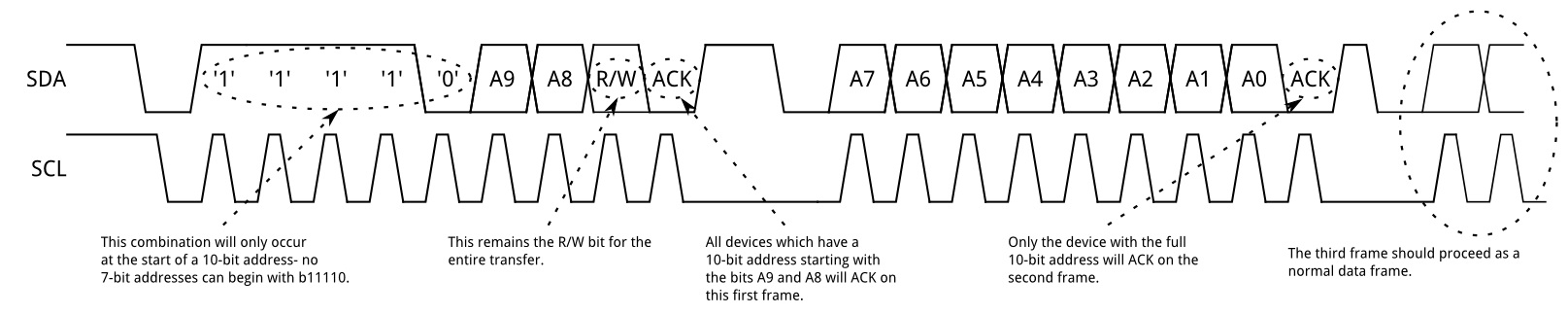
As with a normal 7-bit transfer, another transfer begins immediately, and this transfer contains bits 7:0 of the address. At this point, the addressed peripheral should respond with an ACK bit. If it doesn't, the failure mode is the same as a 7-bit system.
Note that 10-bit address devices can coexist with 7-bit address devices, since the leading '11110' part of the address is not a part of any valid 7-bit addresses.
Repeated Start Conditions
Sometimes, it is important that a controller be allowed to exchange several messages in one go, without allowing other controllers on the bus to interfere. For this reason, the repeated start condition has been defined.
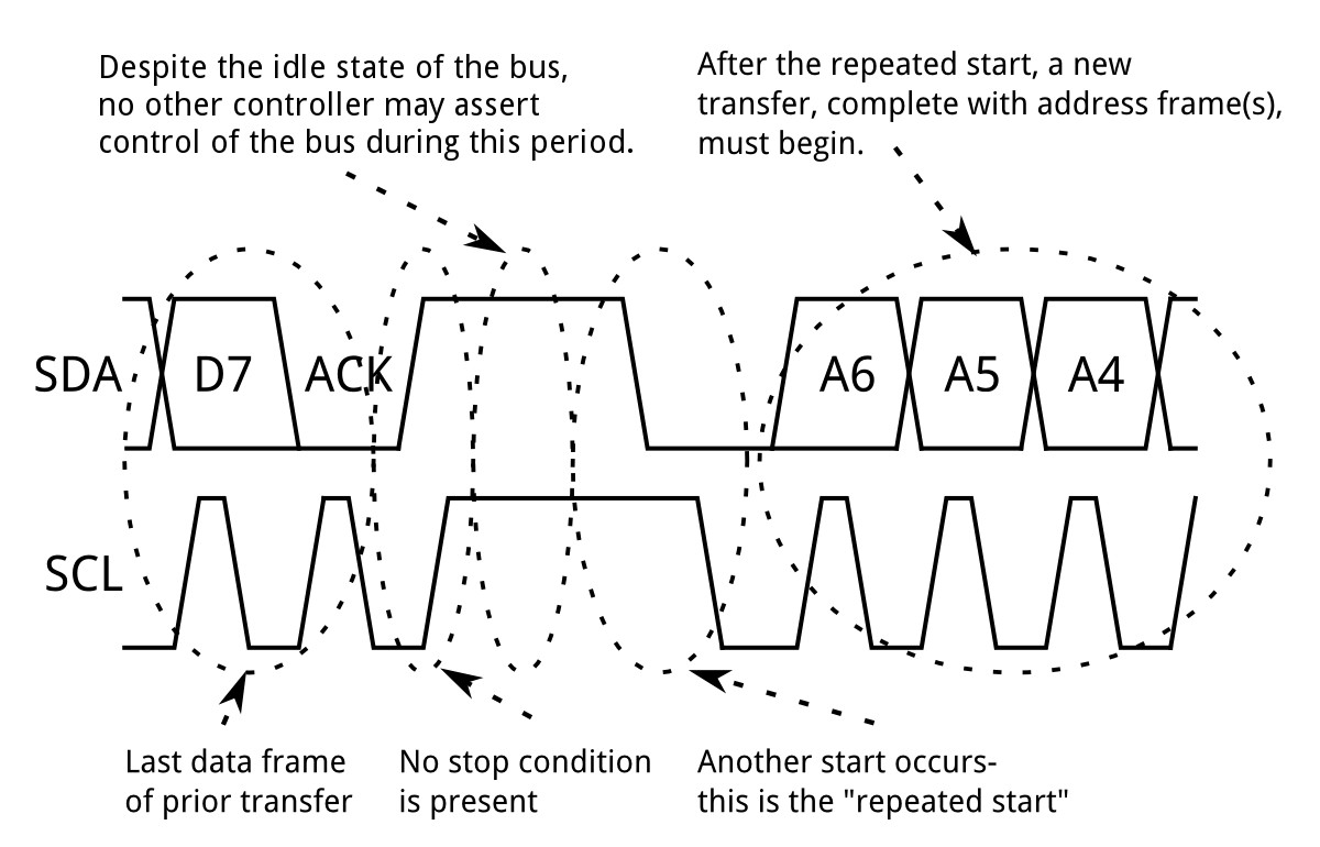
To perform a repeated start, SDA is allowed to go high while SCL is low, SCL is allowed to go high, and then SDA is brought low again while SCL is high. Because there was no stop condition on the bus, the previous communication wasn't truly completed and the current controller maintains control of the bus.
At this point, the next message can begin transmission. The syntax of this new message is the same as any other message--an address frame followed by data frames. Any number of repeated starts is allowed, and the controller will maintain control of the bus until it issues a stop condition.
Clock Stretching
At times, the controller's data rate will exceed the peripheral's ability to provide that data. This can be because the data isn't ready yet (for instance, the peripheral hasn't completed an analog-to-digital conversion yet) or because a previous operation hasn't yet completed (say, an EEPROM which hasn't completed writing to non-volatile memory yet and needs to finish that before it can service other requests).

In this case, some peripheral devices will execute what is referred to as "clock stretching". Nominally, all clocking is driven by the controller — peripherals simply put data on the bus or take data off the bus in response to the controller's clock pulses. At any point in the data transfer process, an addressed peripheral can hold the SCL line low after the controller releases it. The controller is required to refrain from additional clock pulses or data transfer until such time as the peripheral releases the SCL line.
CCS811 Air Quality Breakout Hookup Guide
Interested in learning more foundational topics?
See our Engineering Essentials page for a full list of cornerstone topics surrounding electrical engineering.
