Heartbeat Straight Jacket
 Nate,
Nate,  Toni_K
Jacket Electronics Hookup
We recommend reading over the EL Sequencer Hookup Guide for detailed board information and electrical specifications.
EL Sequencer/Escudo Dos Hookup Guide
Solder Headers
You will need to solder headers onto the EL Sequencer to give yourself programming access. You can either program the board via the FTDI header using the Arduino IDE, or you can use the ICSP header and program the board via AVR-GCC.
For our example, we will be using the FTDI header.
You will also need to solder headers to connect the nRF24L01+ pins and module. We recommend using male headers on the EL Sequencer, and female headers on the nRF24L01+ breakout.
Connect the nRF24L01+ module
Plug the nRF24L01+ module into the headers you previously soldered onto the board. If you prefer to use jumper wires between the two boards, simply plug in wires directly across.
Connect the EL Wire
Plug in the JST connectors of the EL wire into the first 5 channels of the EL sequencer. You can add additional channels of EL wire, but keep in mind that you will need to also modify the code later on.
Connect the Inverter
For this project, we will be using the 3V inverter. Connect the red/black wires to the DC Output header, and connect the black/black wire pair to the AC Input header.
Connect the Power Supply
Since this is a costume, we need to be mobile! Therefore we are using a Lipo battery to as the power supply for this project. We recommend the 2000mAh battery though there are smaller batteries available, depending on the fabric you will be attaching this to. Keep in mind your battery capacity requirements will vary depending on how many wires you have turned on simultaneously and how long you intend the project to run.
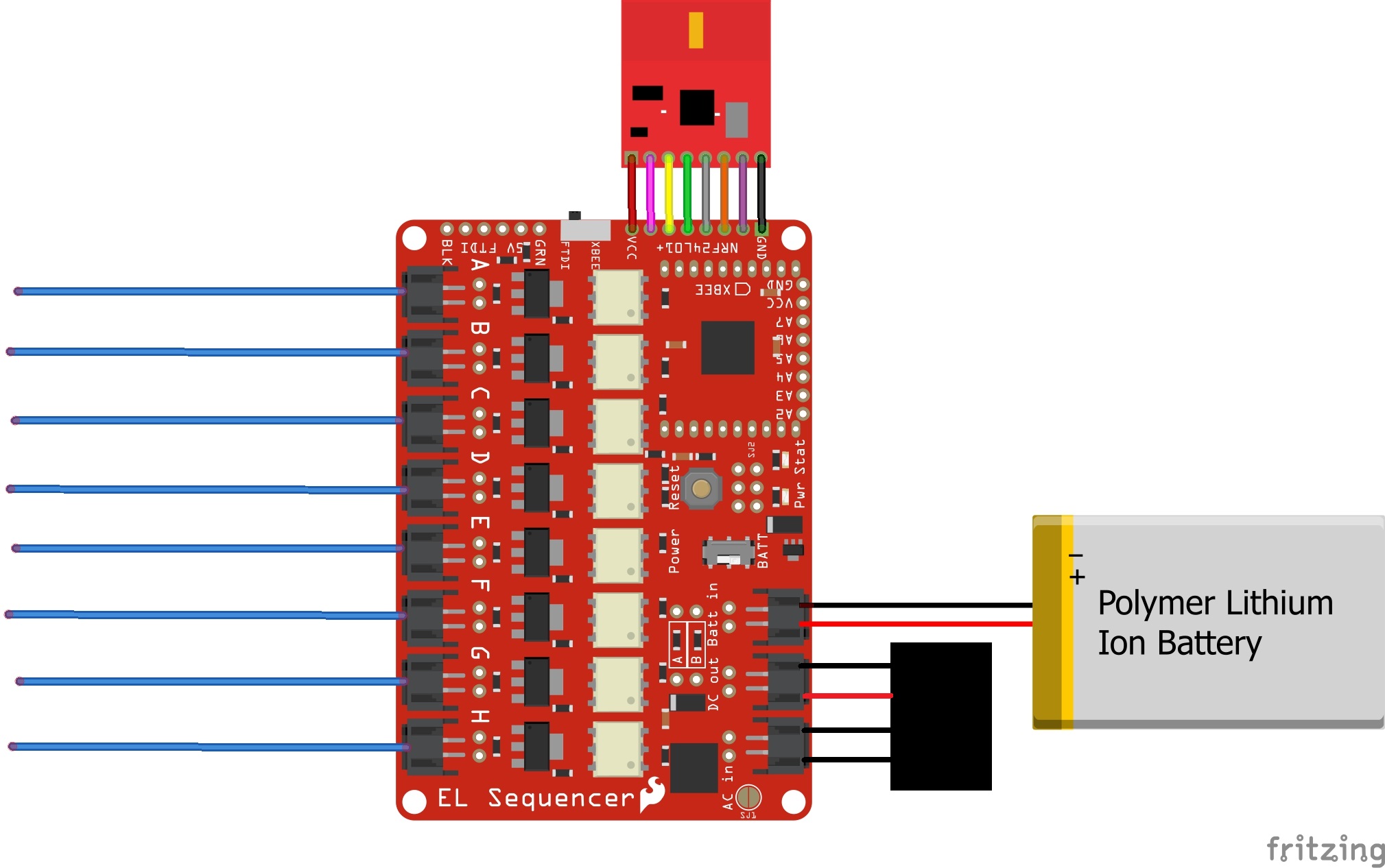
Final Circuit
Once everything is connected, your circuit should look like the following example.
Connect the Electronics and Jacket
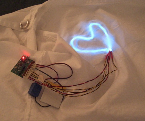
Once you have all of the electronics wired, it's time to attach it to the jacket.
To hide the electronics, we recommend placing those on the inside of the jacket and feeding the EL wire to the outside.
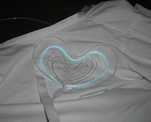
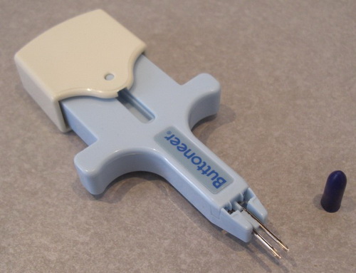
Once the EL wire is on the outside of the jacket, you will need to shape it into hearts. To form and attach the EL wire to the straight jacket, I used the handy Buttoneer. This device uses this neat plastic 'staples' to re-attach buttons to clothing. It also works surprisingly well for attaching EL wire to clothing!
Please check out our EL basics guide for more information on alternative methods of shaping EL wire. When you have the shape of the EL wire laid out, you may need to trim some of the wires down to size.
Once the hearts have all been shaped and attached, the outside of the jacket should look like the following: