Heartbeat Straight Jacket
 Nate,
Nate,  Toni_K
Project Development
Figuring Out How To Use EL Wire
This first thing I had to do was to get my ATmega168 microcontroller to be able to control a single channel. In other words, turn on and off one string of EL wire. EL wire is a bit intense when it comes to control. EL wire requires something like 125V AC at 425Hz. This is a pretty high voltage, and a weird frequency, but with very little current. I might be able to design a circuit to generate this, or I could just buy an inverter.
Connecting the AC inverter to the EL wire, sure enough, it lit up. Now, I wanted control. How do I turn the AC power going to a strand of EL wire on and off? With a TRIAC! These are nifty 'switches' that allow you to turn on/off an AC source. Perfect. I settled on the following part listed below. Cheap, TO92 thru-hole easy to solder, and can handle up to 0.6A at 200V. Wow. Let's hope we don't do anything nearly that big.
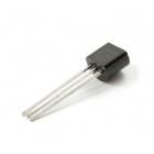
TRIAC
COM-09234The schematic symbol for the TRIACs look similar to the image below.

Here's the DC current readings I found going into the inverter:
- 86mA no load
- 110mA load under control
I found that you could run this inverter without a load, without problems. Results may vary. So you can see that strand of EL wire uses around 25mA(DC) depending on length. On par with LED power consumption.
The next step was to get the wireless working between the straight jacket and the stethoscope. I choose the nRF2401A (Please note this part is now retired. we will be using the nRF24L01+ for this example). These low power, low cost ICs are great for a simple 'Hey! Beat the heart' type signal. The signal that will be broadcast by the stethoscope is a low data rate (I need something like 4 bytes) and low bandwidth (4 bytes * ~70 beats per minute).
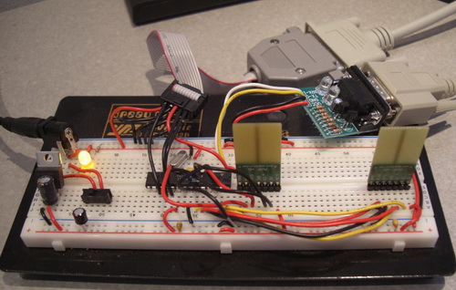
Initially, I used two radios in the same breadboard so that I could get firmware sending and receiving. Eventually, I boiled all this down to a few nRF libraries that work pretty well. When in doubt, RTFM for the Nordic ICs.
Control Boards
Now using all this learned knowledge from the breadboard of the triac and the radios, I created two PCBs, the EL-controller and the Stethoscope transmitter.
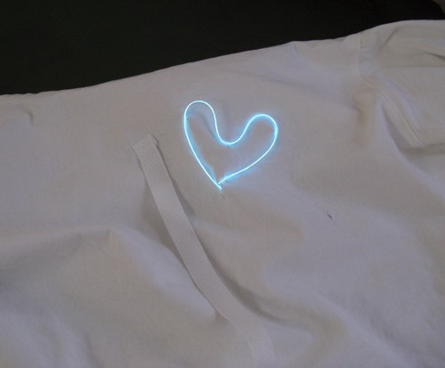
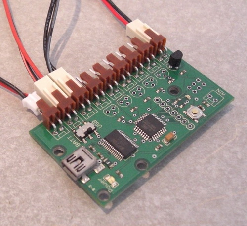
The EL sequencer receives RF triggers and controls the EL strings. In this case, each channel is an EL wire in the shape of concentric hearts.
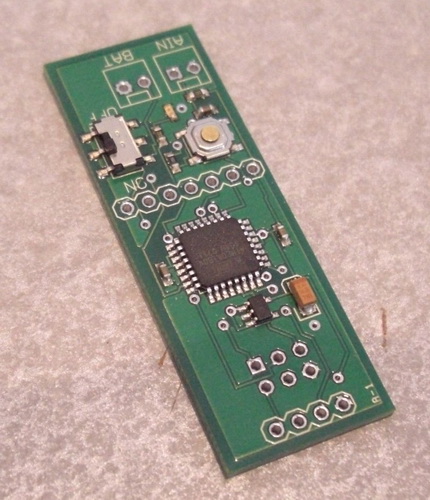
The Stetho RF board that goes into the stethoscope had to be made as small as possible. It is powered by a small lithium polymer battery and does nothing but read the analog level on the microphone in an attempt to pick up and heart beat, and broadcast a 'Hey! Beat the heart' signal to the straight jacket.
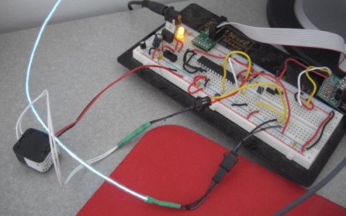
Now some testing! The first step was to get the EL sequencer to control one string, within the jacket:
Here is the sequencer hooked up to LiPo, inverter power, AC output, and one string there on the end.