Hackers in Residence: The Sound Visualizer
 onebeartoe
Introduction
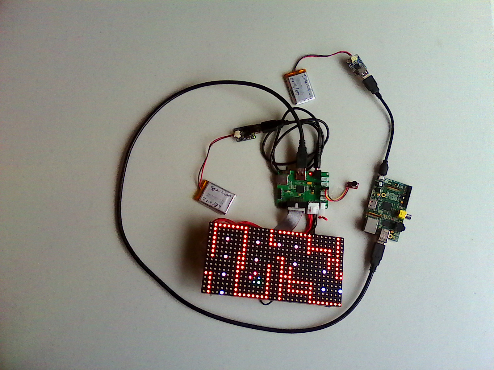
This tutorial shows how to put together a sound visualizer that I created, during my time in the SparkFun HIR program. The end goal for the project was to have a sound reactive LED belt buckle. To accomplish the task of sound visualization, a Raspberry Pi drives and communicates with a Pixel Board over USB. The Pixel takes input from a microphone (or the SparkFun Sound Detector) and passes it back to a Java application running on the Raspberry Pi. The Java application then processes the sound input values and sends commands to the Pixel to drive the RGB LED panel.
Required Materials
Here is a list of SparkFun parts used in this project, if you would like to follow along.
Additional Supplies
Also used in this project is the Pixel Board, which is used to control LED matrices. More info on this product can be found here.
Data Connection
The Raspberry Pi needs a serial connection to the Pixel. A male to male USB cable is needed for this connection.
Power
Often the Raspberry Pi is powered from wall Adapter Power Supplies. However, for this project, I wanted the entire setup to be mobile/wearable. Thus, LiPo batteries were used to power the Raspberry Pi and the Pixel Board in conjunction with some boost circuitry. You could also use a beefy battery pack, such as this one, to power this project on the go.
Suggested Reading
Before diving into this project, you may want to check out these other tutorials first.
- Connector Basics
- Light-emitting Diodes (LEDS)
- How LEDs Are Made
- RGB Panel Hookup Guide
- Serial Communication