Getting Started with the micro:bit
 D___Run___, Ell C
Hardware Overview
There are two versions of the BBC micro:bit and both have a lot to offer when it comes to onboard inputs and outputs. In fact, there are so many things packed onto these little boards that you would be hard pressed to really need anything else if you were looking at just exploring the basics of programming and hardware.
Front
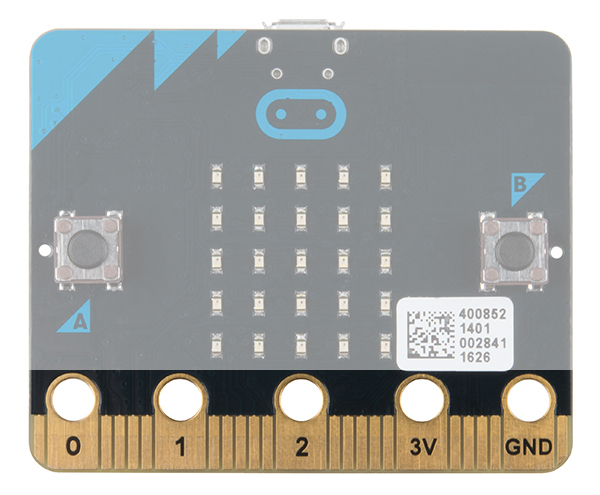
On the front of the board there are a number of components that are pretty visible right off the bat!
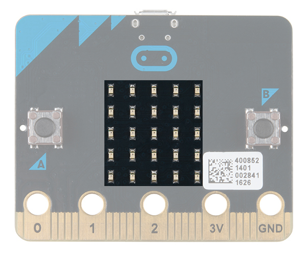
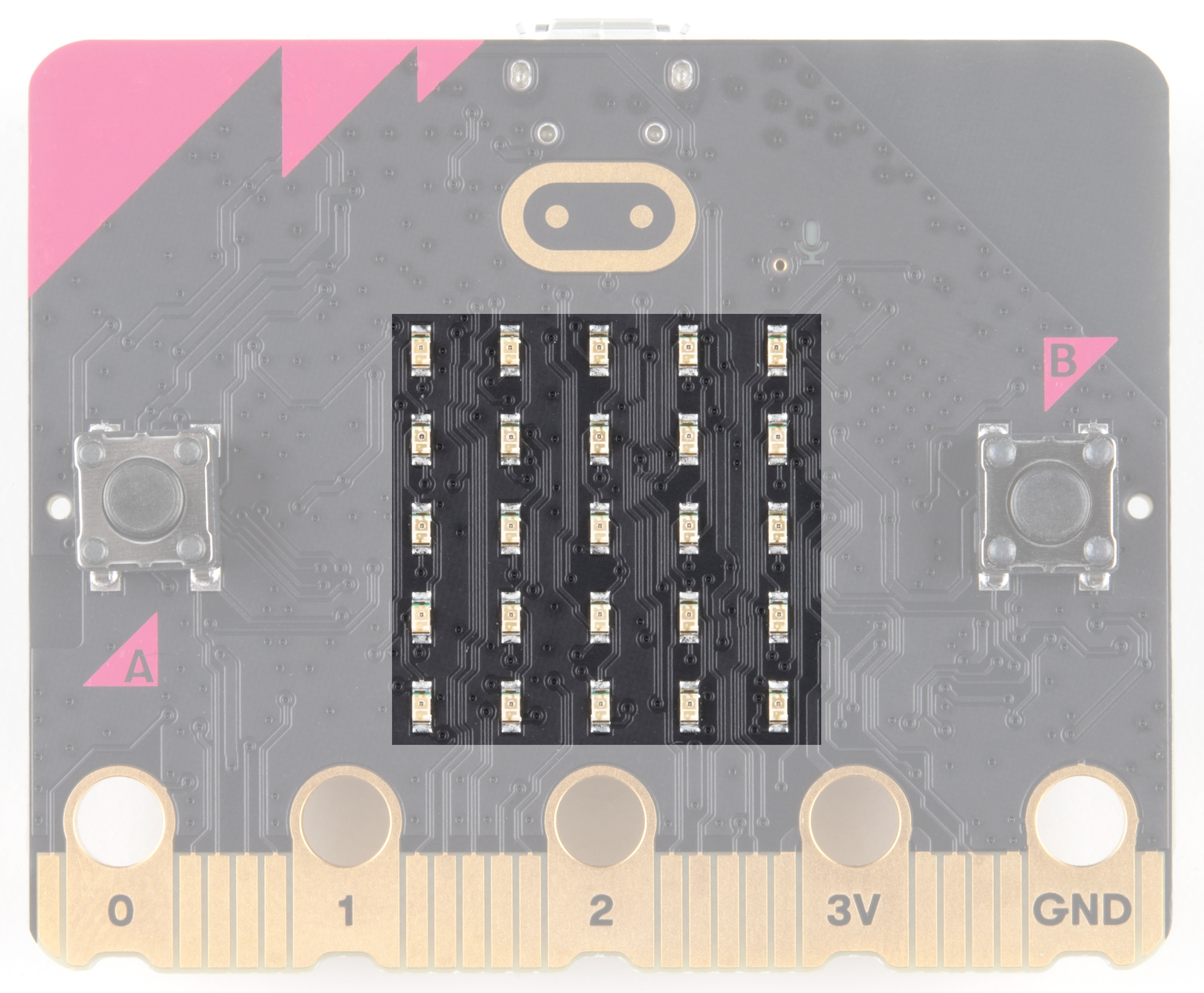
LED Array
The micro:bit has a 5x5 LED array that you can use as a tiny screen to draw on and display words, numbers and other information.
 |
 |
| LED Array on micro:bit | LED Array on micro:bit V2 |
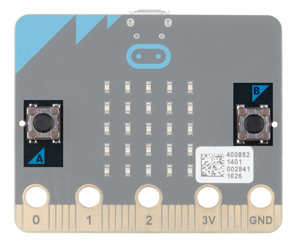
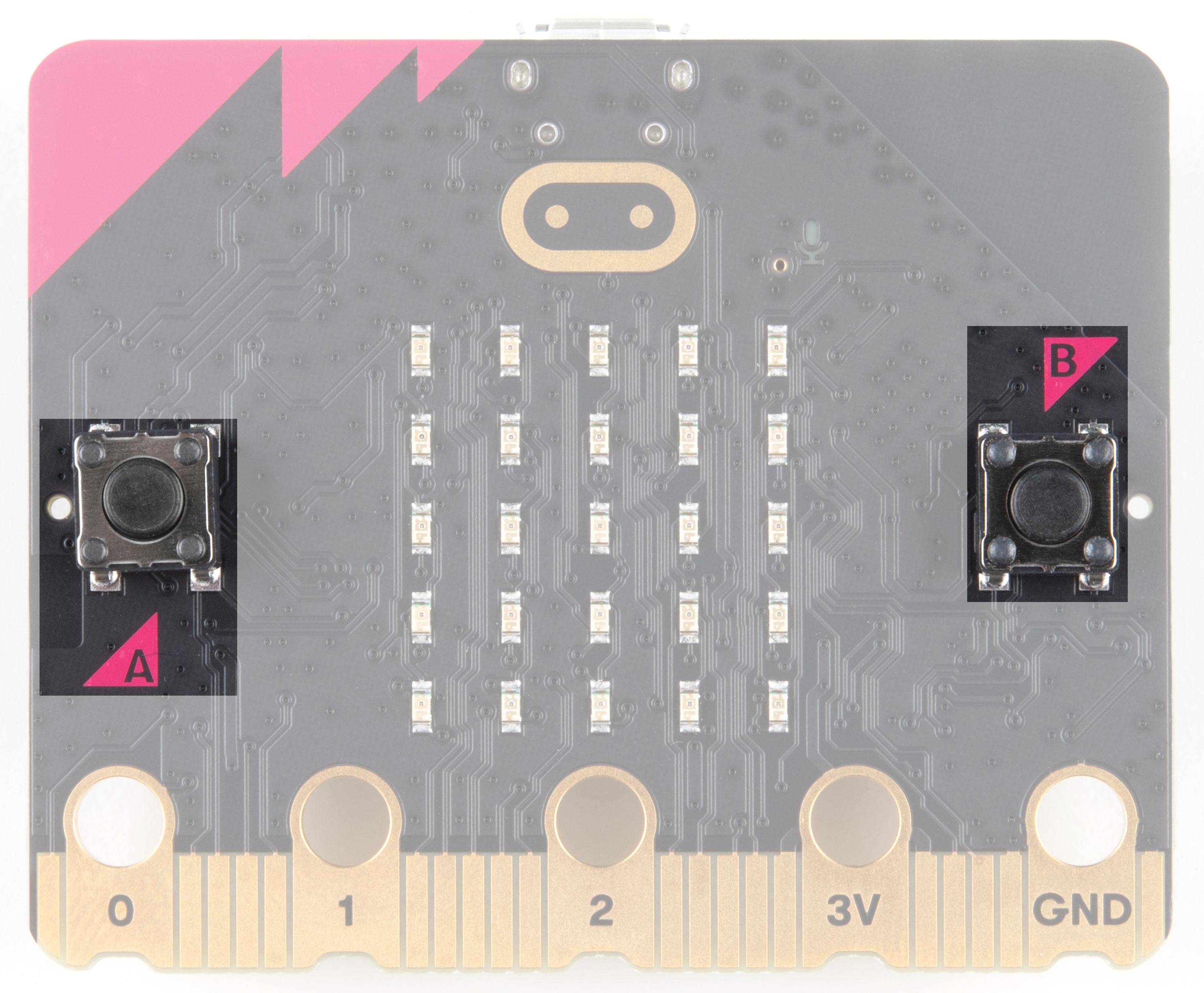
A/B Buttons
Two buttons in all of their clicky glory: A is on the left, B is on the right, and both are prime for controlling a game of your design.
 |
 |
| A/B Buttons on micro:bit | A/B Buttons on micro:bit V2 |
Edge "Pins"
The gold tabs at the bottom of the board are for hooking up external components. The tabs with larger holes can be easily used with alligator clips to prototype things quickly! To access all the pins, you will need a board with an edge connector. For breadboard prototyping, you'll want the micro:bit breakout with headers. In micro:bit v2, you will also notice that they are notched for easier connection with alligator clips.
 |
 |
| Edge Pins on micro:bit | Edge Pins on micro:bit V2 |
 |
 |
Light Sensor
A bit of a hidden gem. The LED array doubles as a light sensor!
|
|
| Light Sensor on micro:bit | Light Sensor on micro:bit V2 |
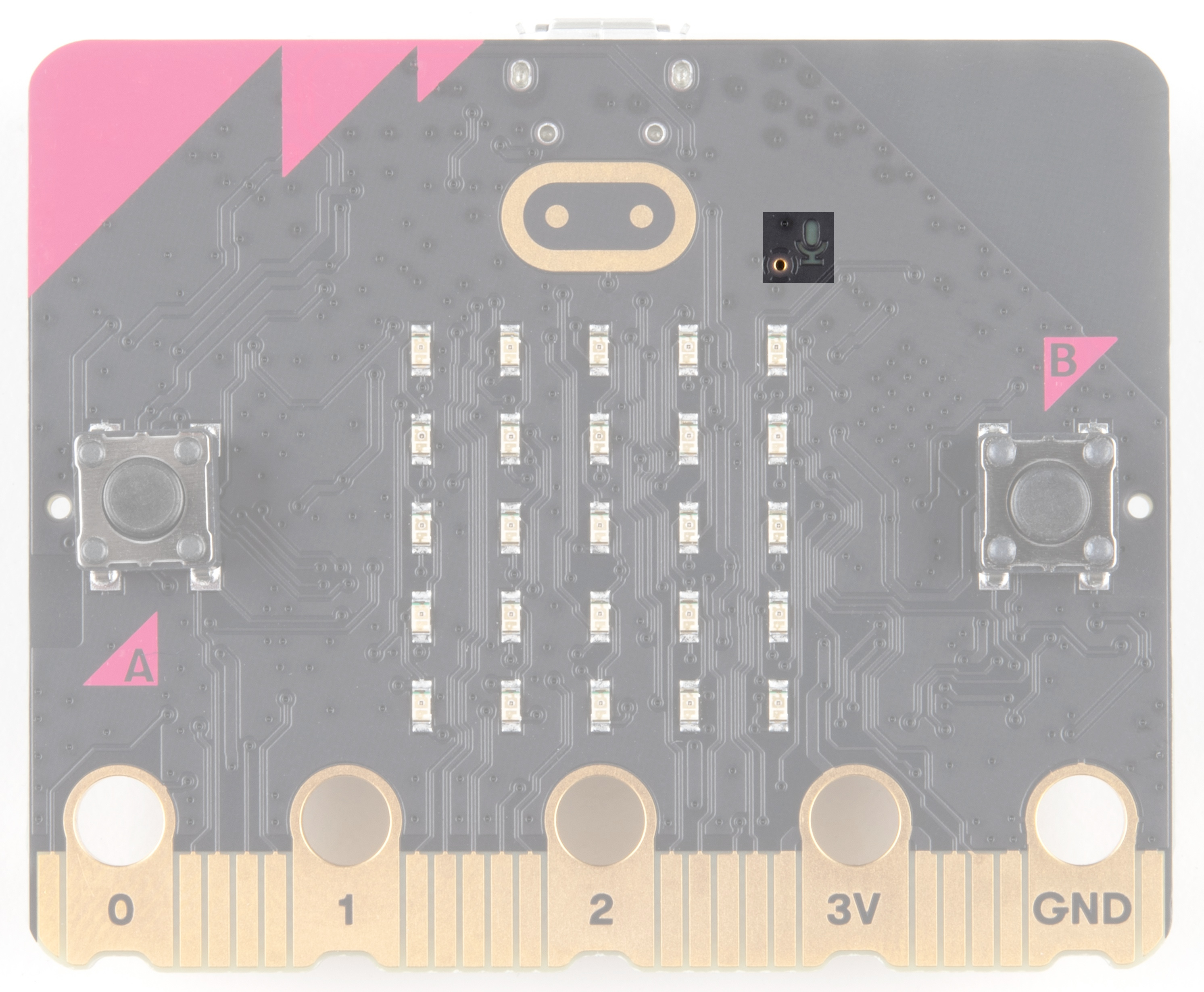
V2 Only - Microphone Input and LED Indicator
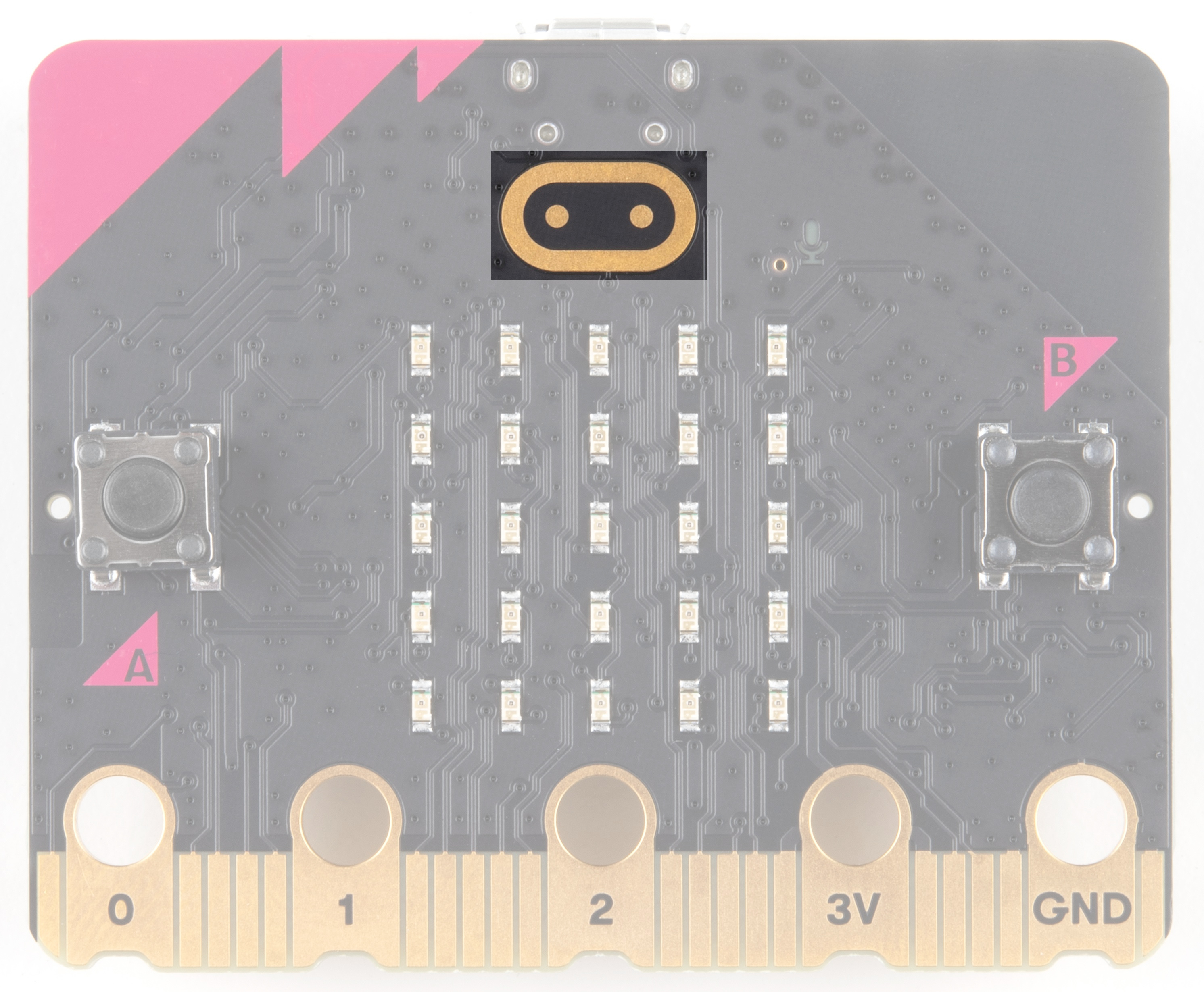
V2 Only - Touch Sensitive Logo
The gold logo is a capacitive touch sensor that works a bit like a touch screen on a mobile phone, measuring tiny changes in electricity.
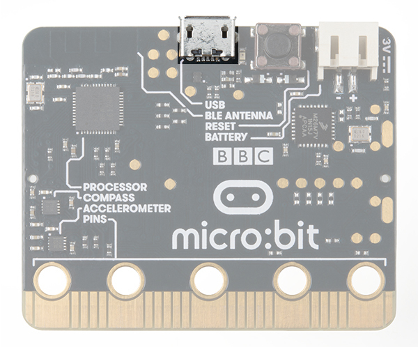
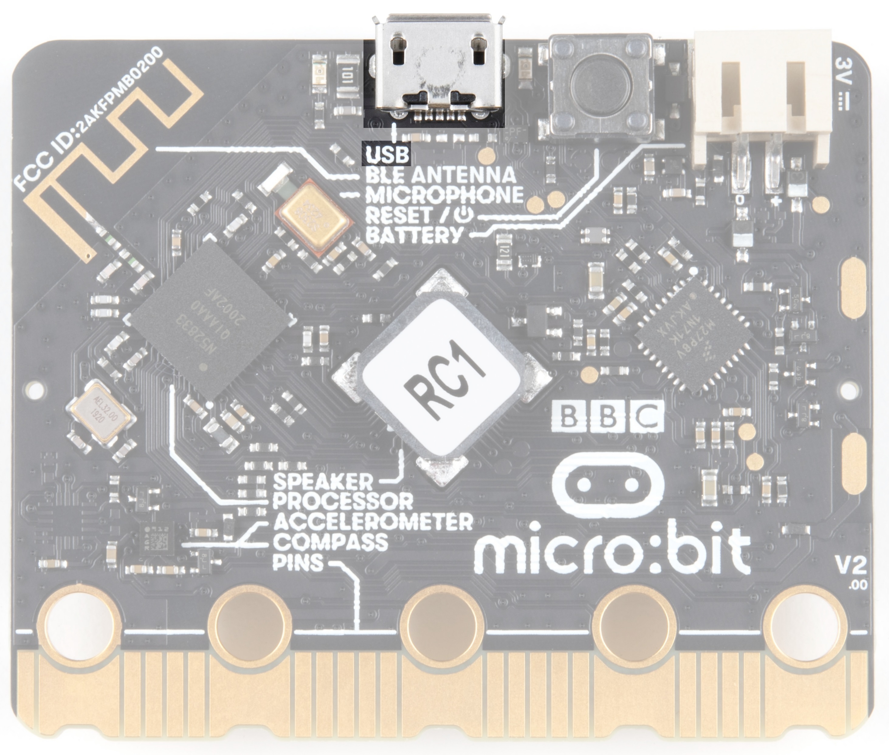
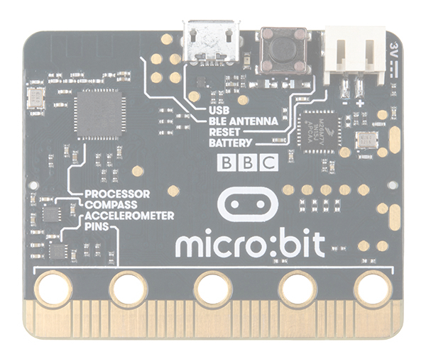
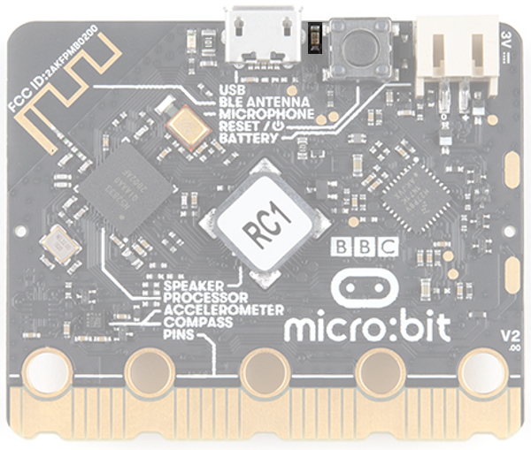
Back
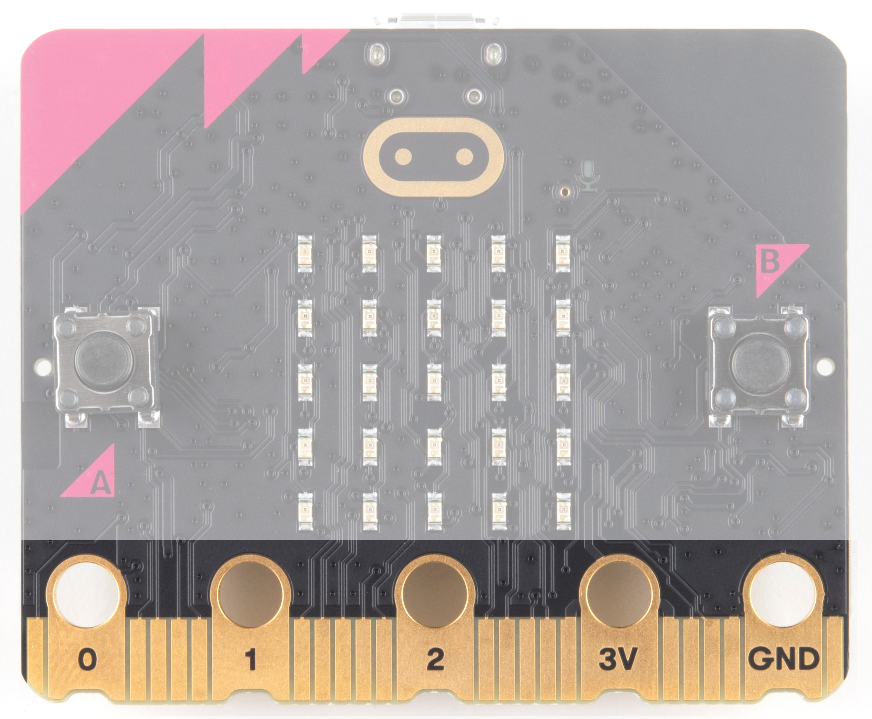
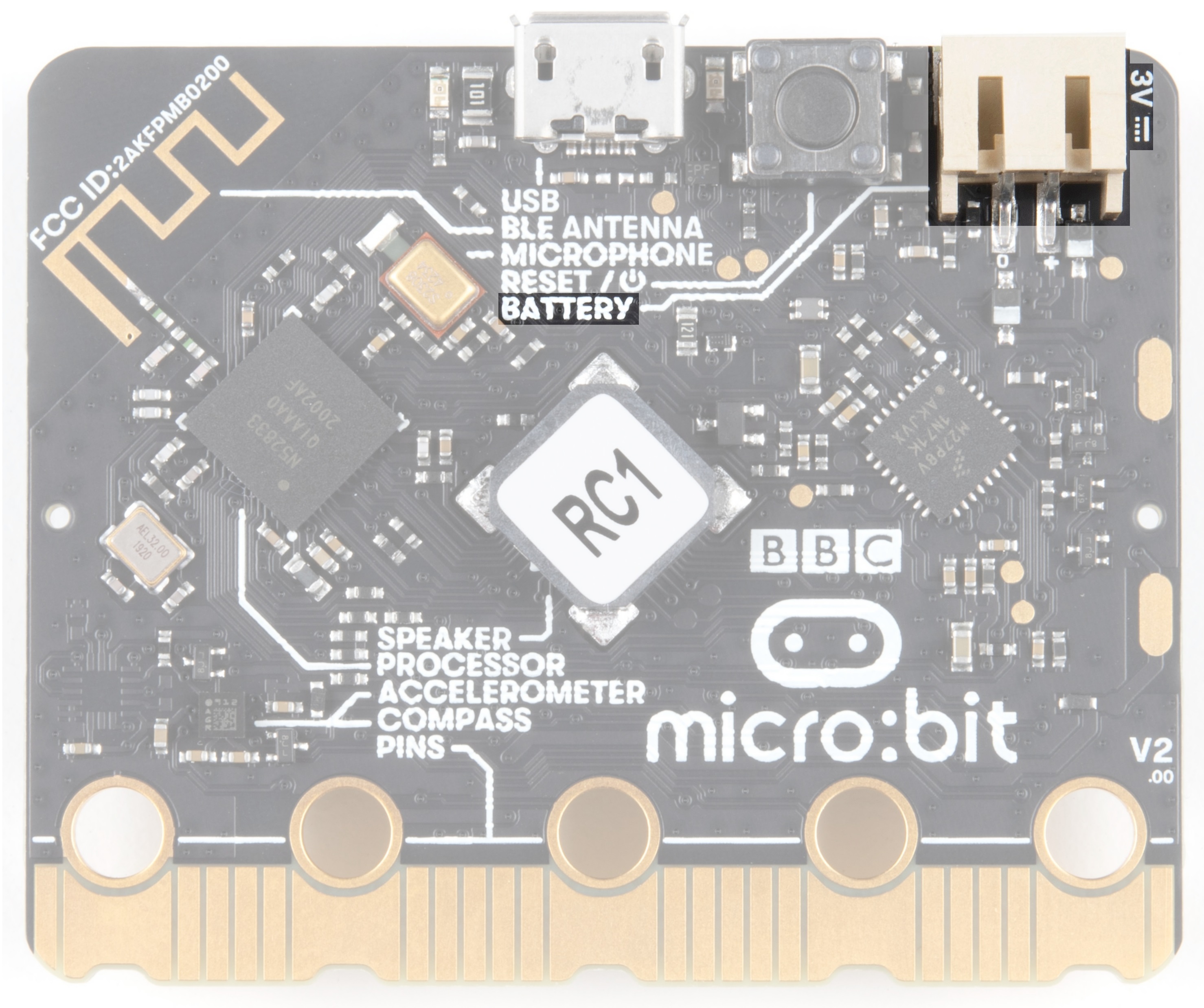
The back is where a lot of the magic happens. Check it out...
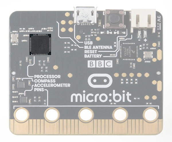
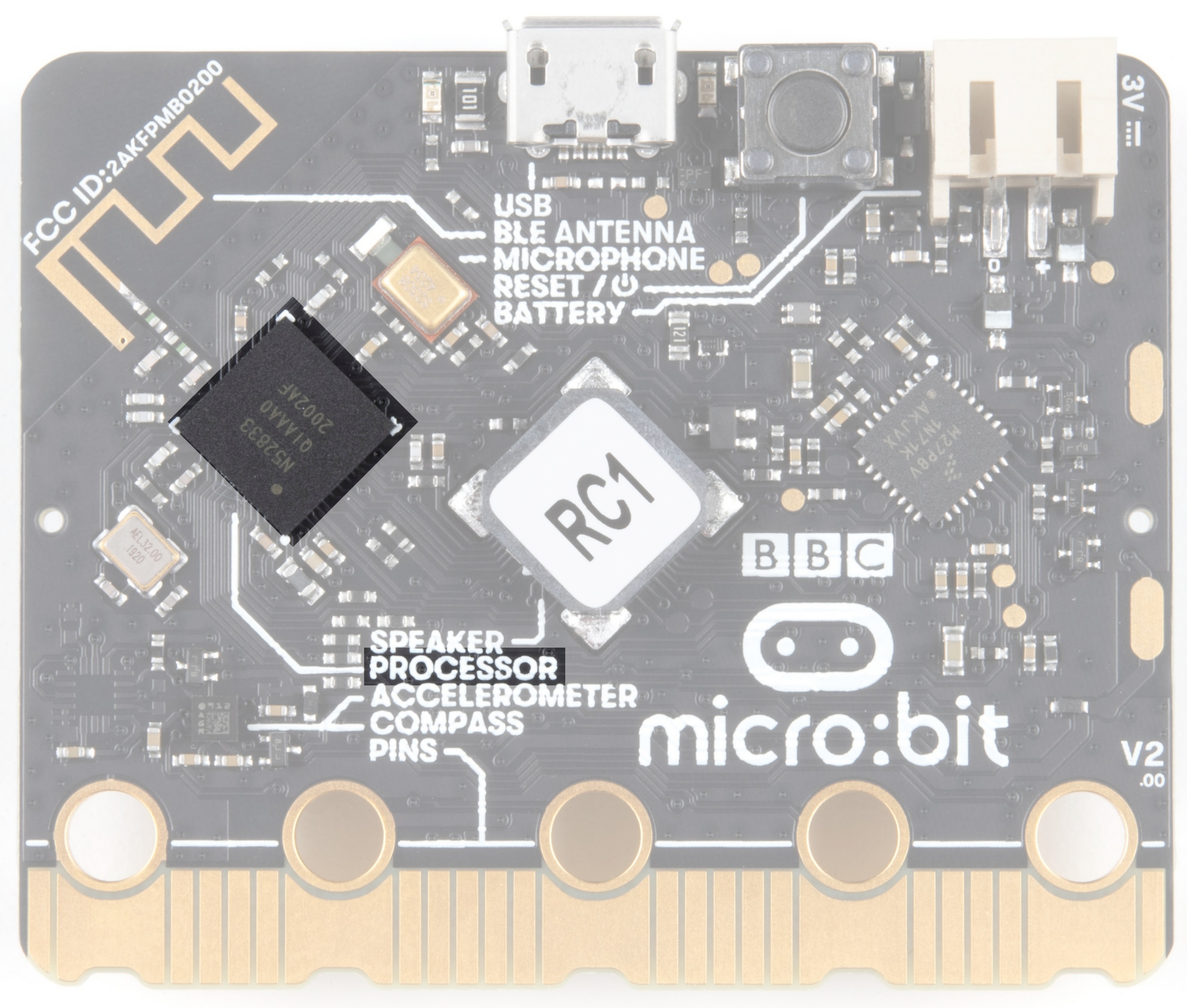
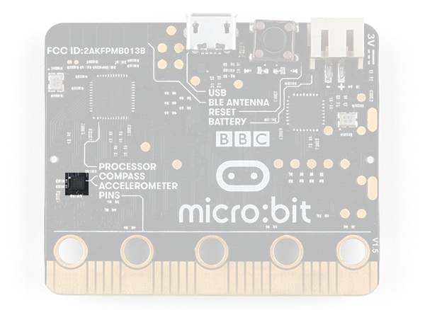
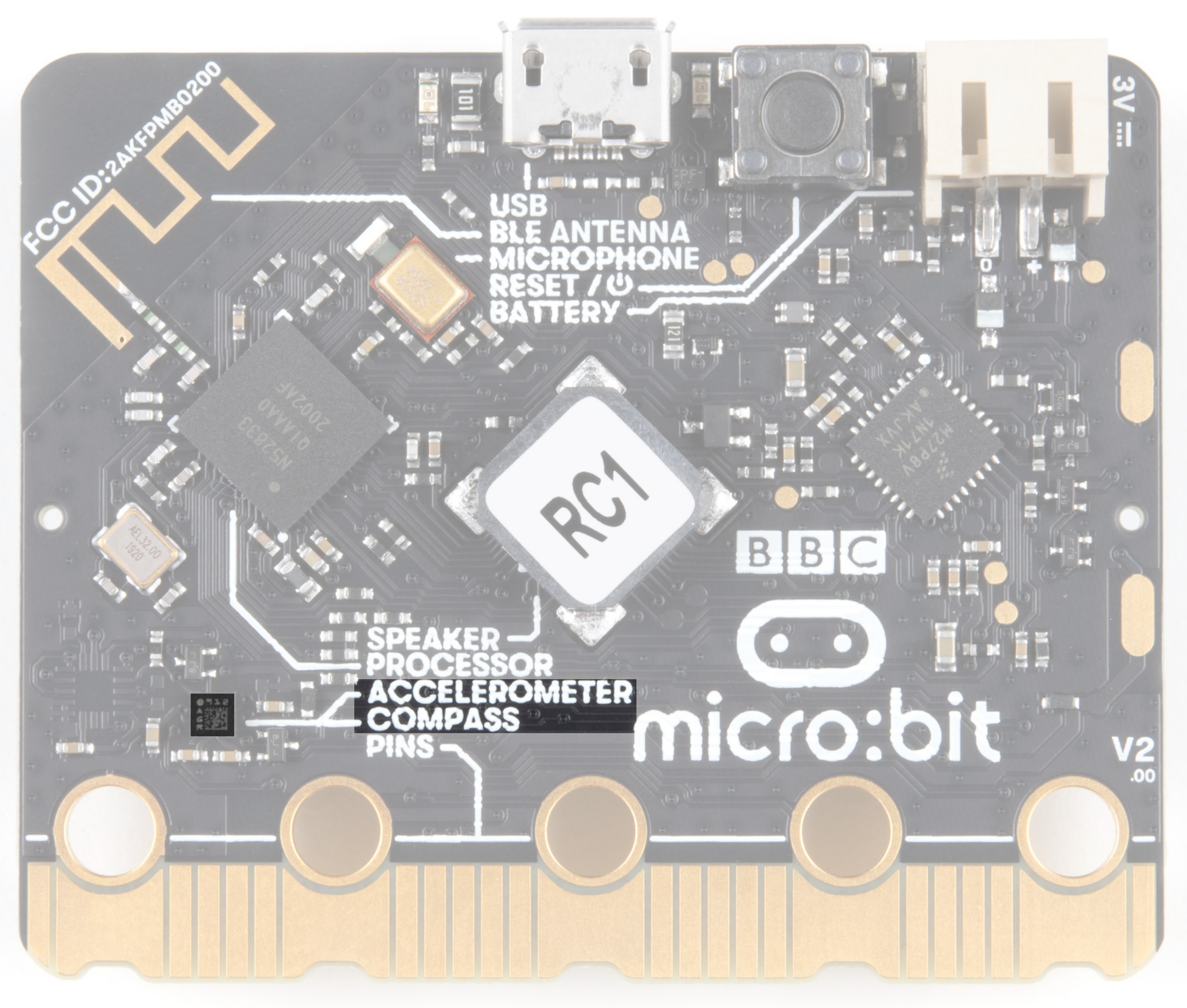
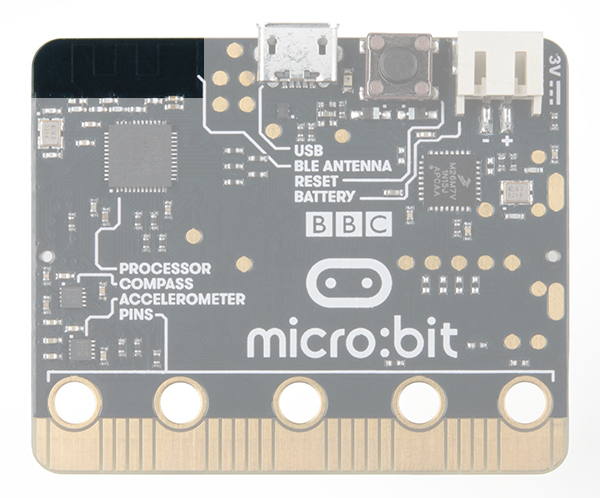
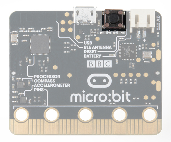
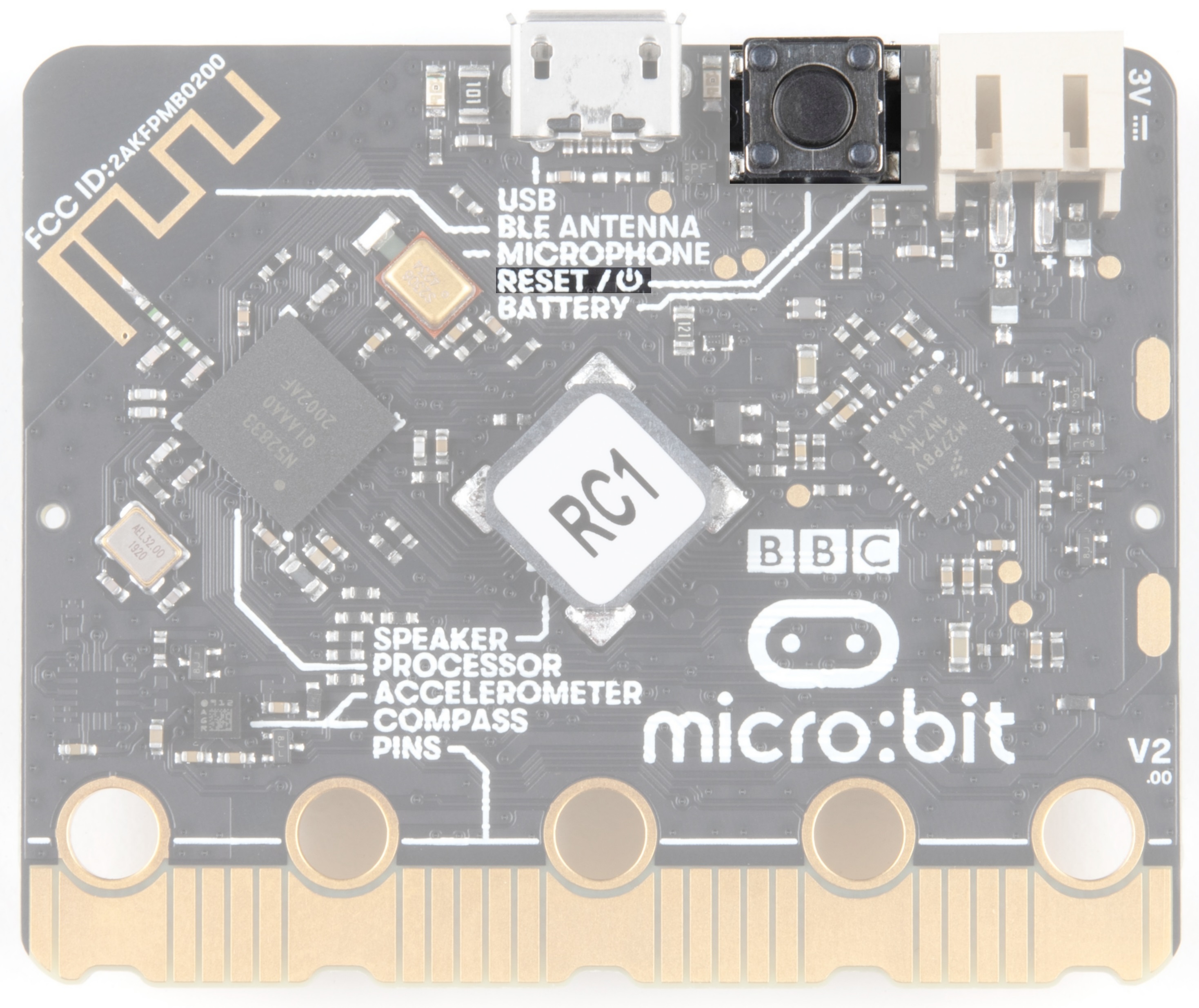
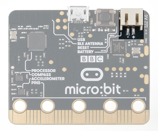
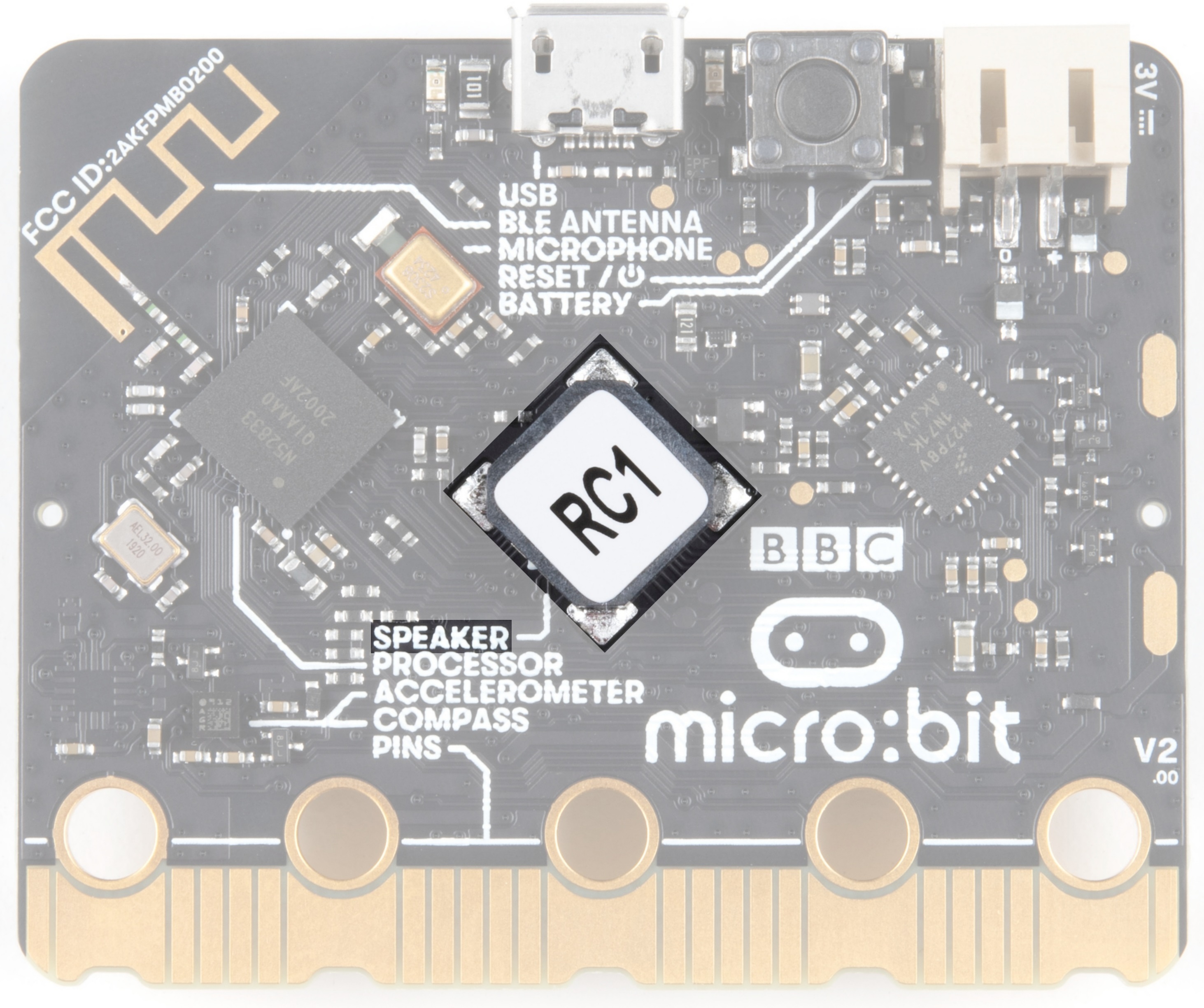
Microcontroller
The brains of the outfit.
The micro:bit is powered by a 16MHz ARM Cortex-M0 microcontroller with 256KB Flash and 16KB RAM.
The micro:bit v2 is powered by Nordic Semiconductor's nRF52833 chip - a 64MHz ARM Cortex-M4 microcontroller with FPU, 512KB Flash, and 128KB RAM.
 |
 |
| nRF51822 Processor on micro:bit | nRF52833 Processor on micro:bit V2 |
Accelerometer/Compass
The micro:bit has an onboard accelerometer that measures gravitational force, as well as a compass (a.k.a. a magnetometer) that can detect its orientation using Earth's magnetic field.
 |
 |
| Accelerometer and Magnetometer on micro:bit | Accelerometer and Magnetometer on micro:bit v2 |
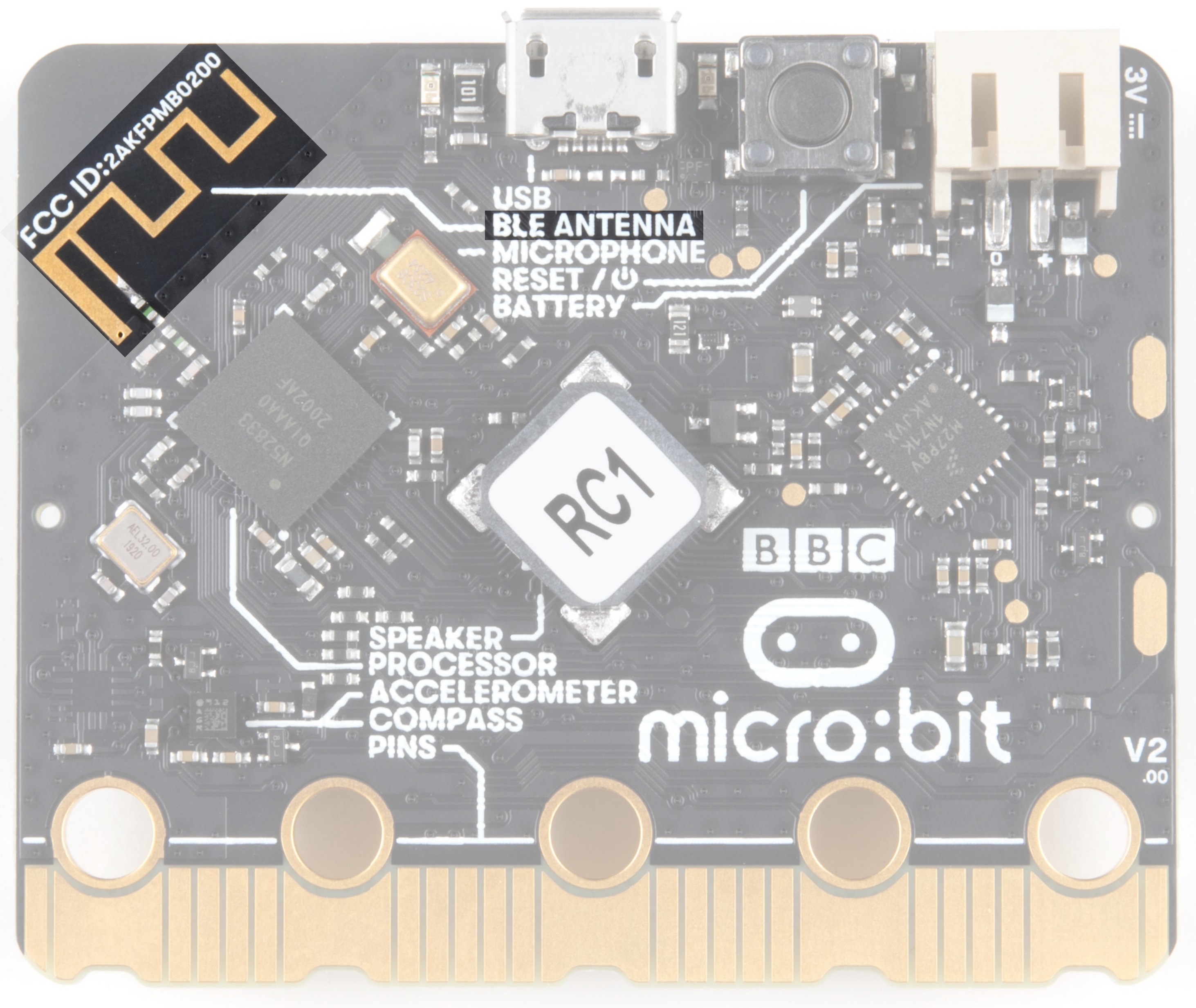
Bluetooth/Radio
Communication is huge with the micro:bit. You can communicate with your phone or tablet using Bluetooth Low Energy (BLE) or between two or more micro:bits using the standard 2.4GHz "radio". Note that the micro:bit v1 uses BLE Bluetooth v4.0 while micro:bit v2 uses BLE Bluetooth v5.0.
 |
 |
| Bluetooth / Radio Antenna on micro:bit | Bluetooth / Radio Antenna on micro:bit v2 |
Temperature Sensor
No, the drawing is not highlighted incorrectly! The microcontroller doubles as a temperature sensor!
|
|
| Microcontroller as Temperature Sensor on micro:bit | Microcontroller as Temperature Sensor on micro:bit v2 |
USB Port
Used to upload code to your micro:bit or power from your computer or laptop. You can also send and receive serial data from the MakeCode Serial Console or a Serial Terminal.
 |
 |
| USB Port on micro:bit | USB Port on micro:bit v2 |
USB Activity LED Indicator
When there is activity on the USB pins, the LED on the right will light up.
 |
 |
| USB Activity LED Indicator on micro:bit | USB Activity LED Indicator on micro:bit v2 |
V2 Only - Power LED
V2 of the micro:bit also includes a power LED next to the USB connector to indicate power is available.
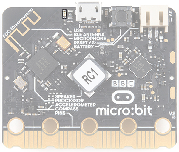
Reset Button
A button to reset your micro:bit and start your code over from the beginning.
 |
 |
| Reset Button on micro:bit | Reset/ Power Button on micro:bit v2 |
JST Battery Connector
A connector to hook up an external battery pack to your micro:bit.
 |
 |
| JST Connector on micro:bit | JST Connector on micro:bit v2 |
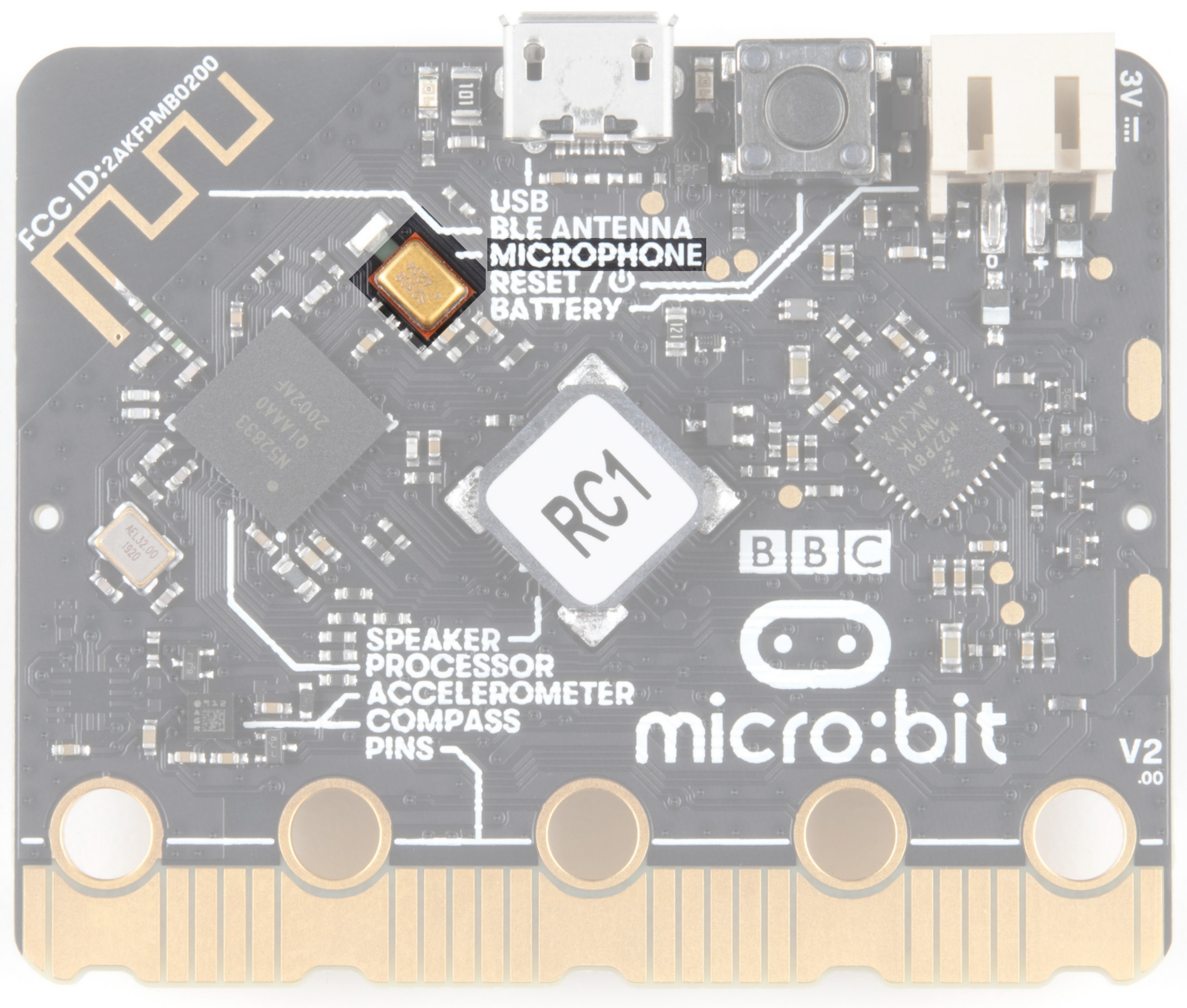
V2 Only - Microphone
V2 of the micro:bit contains a MEMS microphone to allow sound-sensing without the need to attach another device. If you look back at the front of the board, you will notice that the microphone input leads to this component on the back.
V2 Only - Speaker
V2 of the micro:bit also includes a built-in speaker on the back of the board. For users using an external speaker on the edge pins, you will need to configure the built-in speaker in the programming language of your choice.
Phew! That is a lot of bells and whistles...a true Swiss army knife!