Getting Started with MicroMod
 Nate
Nate 
Introduction
MicroMod is a compact interface to connect a microcontroller to various peripherals. You can generally think of the MicroMod system as a ‘brain’ plugging into a ‘carrier board’.
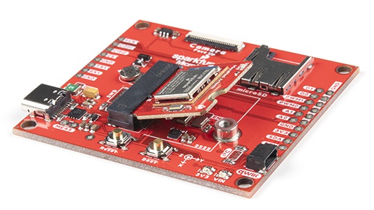
A MicroMod processor board is approximately 22x22mm and can insert into any MicroMod carrier board. A small screw holds the processor board in place. Whereas the original M.2 standard was designed for swapping out peripherals (user could change one solid state hard drive to a larger one) the MicroMod standard is designed for swapping out controllers (user can start with a powerful processor and then change to a low power controller to extend battery life).
Suggested Reading
If you aren't familiar with the MicroMod ecosystem, we recommend reading here for an overview.
| MicroMod Ecosystem |
If you aren’t familiar with the following concepts, we recommend checking out these tutorials before continuing.