Getting Started with MicroMod
Designing with MicroMod
Can I Make My Own MicroMod Processor Board?
Absolutely. SparkFun is an open source hardware company and is not patenting this interface. All we ask is that you don’t fork the spec, follow the rules, and try not to muddy the community by introducing competing or partially compatible similar interfaces.
We recommend starting from one of our open source processor board designs. Currently all these files are EAGLE PCB format. If you have a different PCB package and you'd like to add your design to the list as a reference design please let us know!
Additionally, we've written Designing with MicroMod that goes into depth about how to create a good processor and carrier board.
Can I Make My Own MicroMod Carrier Board?
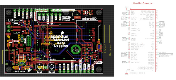
Absolutely! This where things get really exciting. We’ve got a variety of resources including a connector footprint and symbol for Eagle PCB. We had multiple carrier boards already designed and open source so you can use them as a reference design and starting point. We can’t wait to see what you make.
We recommend starting from one of our open source carrier board designs. Currently all these files are EAGLE PCB format. If you have a different PCB package and you'd like to add your design to the list as a reference design please let us know!
- MicroMod All The Pins (ATP) Carrier Board
- MicroMod Data Logging Carrier Board
- MicroMod Machine Learning Carrier Board
- MicroMod Input and Display Carrier Board
Additionally, we've written Designing with MicroMod that goes into depth about how to create a good processor and carrier board.
When designing your own carrier board keep these rules of thumb in mind:
- All carrier boards must provide a regulated 3.3V supply capable of 1A.
- All carrier boards must provide a USB D+/- connection for programming.
- Not all processor boards have connections to every pin.
- The A0/1, PWM0/1, and D0/1 should be supported by every processor board so you can trust that those pins will be available.
- UART1, SPI, and I2C ports are super common and on nearly every processor board, but peripherals beyond those varies between processor boards. For example: support for a 2nd I2C port varies a lot so if your carrier board requires the 2nd I2C port be aware of what processor boards will be supported.
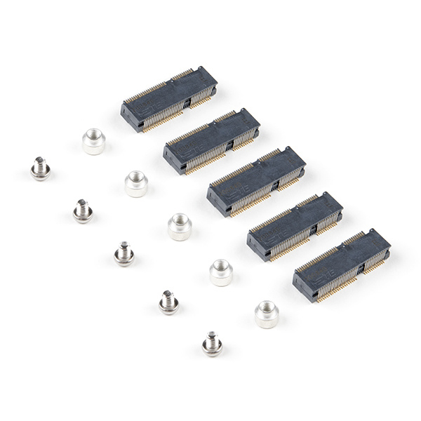
To help get you started with your own custom carrier board we've put together the MicroMod DIY Carrier Kit that includes 5 of the connector, screw, and standoff so that you can get all the ‘special’ parts you may need to make your own carrier board.
The M.2 connector has a 0.5mm pitch and alignment pegs. Hand stenciling and reflow-at-home is possible but we recommend using a stainless steel stencil (do not use mylar) and a higher quality reflow oven (sorry hot plate!) to help prevent jumpers.
Tell Me about Heat Sinking!
One of the benefits to the M.2 standard is the ability to put components under the module. Using this we can now add heatsinks to our microcontrollers!
For this reason we recommend the connector with 4.2mm height. TE makes the 2199230-4 that is widely available and for reasonable cost (1k budgetary pricing is $0.56).
What if I Need A LOT of GPIO?
There are applications where a user will need more than 12 GPIO. The MicroMod specification is flexible. If you would like to design a MicroMod that has only a few peripherals connected (for example, just UART and I2C) and leaving the rest for GPIO (45 available for GPIO in this example) that’s fine. Your carrier board would utilize the UART and I2C pins in the normal location and GPIOs in non-standard locations. This would prevent other MicroMods from being absolutely compatible (perhaps one or two of the MicroMod Artemis would not be able to drive your carrier board’s relays) but it’s allowed. You, the designer, just need to think about the tradeoffs.
We’ve written a guide for creating a MicroMod Processor Board but here are the guiding principles:
- Connect dedicated hardware of the microcontroller to the available I2C, SPI, UART, USB, USB_HOST, CAN, SDIO, and JTAG pins exposed on the MicroMod connector edge.
- Next, A0/A1 on the MicroMod connector edge should be assigned to pins on the microcontroller that are exclusively ADC (no PWM capability).
- PWM0/PWM1 should be assigned to pins that are exclusively PWM (no ADC capability).
- D0/D1 should be assigned to pins that are exclusively GPIO (no ADC or PWM capability)
- Remaining pins should be assigned to Gx with ADC + PWM capable pins given priority (0, 1, 2, etc) positions
- The intent is to guarantee PWM, ADC, and Digital Pin functionality on those specific pins. Whereas Gx pins do not guarantee ADC/PWM function.
- If the microcontroller lacks a specific pin function, and has left over GPIO, they can be over-ruled with GPIO. For example, CTS/RTS can be overwritten with a GPIO if the microcontroller does not have flow control.
For more information, check out the Designing with MicroMod tutorial.

