Fading with the MOSFET Power Switch and Buck Regulator
 Christo-boots with the-pher,
  bboyho
 Introduction
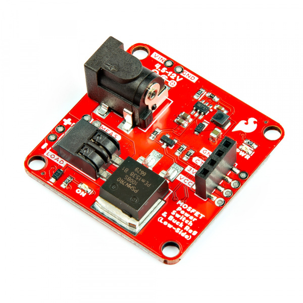
This tutorial will guide you through using the SparkFun MOSFET Power Switch and Buck Regulator (Low-Side) with your Arduino projects. This handy board combines a MOSFET switch for controlling high-power loads (up to 12V) with a built-in buck regulator that conveniently provides stable 3.3V power for your Arduino.
We'll explore various functionalities, starting with basic on/off control and progressing to creating dimming effects for LEDs and controlling motors with variable speeds. By the end, you'll be able to safely manage powerful components and add exciting features to your Arduino projects!
If you are looking for the full Hookup Guide for the SparkFun MOSFET Power Switch and Buck Regulator (Low-Side), click the button bellow. This guide only covers a simple project to get you started quickly, while the full Hookup Guide goes over every detail of the sensor.
Hardware Needed
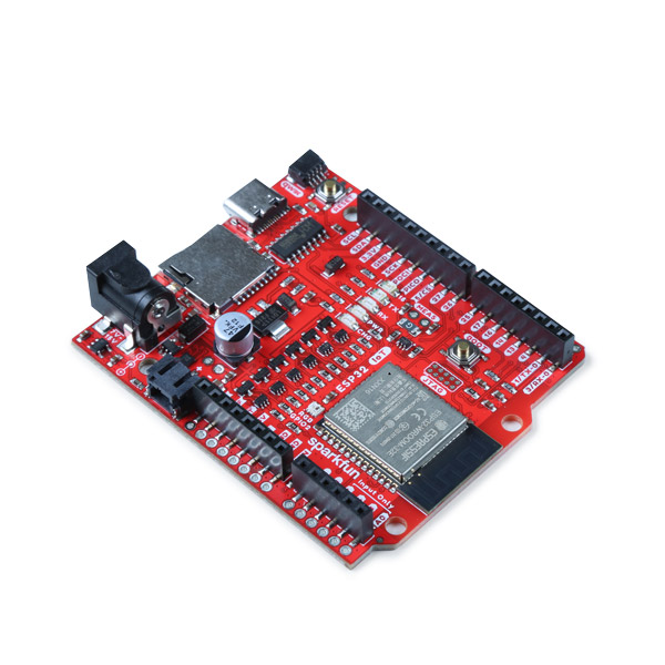
To follow this experiment, you will need the following materials. While this is a simple project we wanted to make sure that you have everything you need to get started before we get to the code. For this simple project we chose the ESP32 IoT RedBoard Development Board.
Software Setup
SparkFun has written a library to work with the SparkFun MOSFET Power Switch and Buck Regulator. You can obtain this library by clicking on the button below, or by downloading it from the GitHub Repository.
Fading
In this example, we will slowly turn on the load and then slowly turn it off using the N-channel MOSFET. This example is better with a DC motor and 12V LED. You will typically want the solenoid to be fully turned on/off.
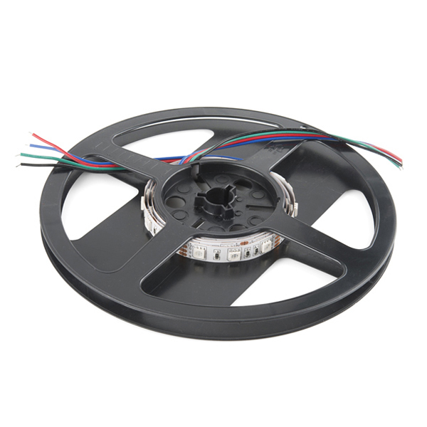
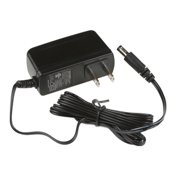
For this example you will need the SparkFun IoT RedBoard - ESP32 Development Board, a USB-C Cable, the SparkFun MOSFET Power Switch and Buck Regulator (Low-Side), a Mini Screwdriver, M/M Jumper Wires, an RGB LED Strip, and a [12V Wall Adapter Power Supply](12V Wall Adapter Power Supply).
Hardware Hookup
You will need to connect everything as explained earlier. For this particular example, we will use one channel from a 12V RGB LED strip as shown in the circuit diagram below.
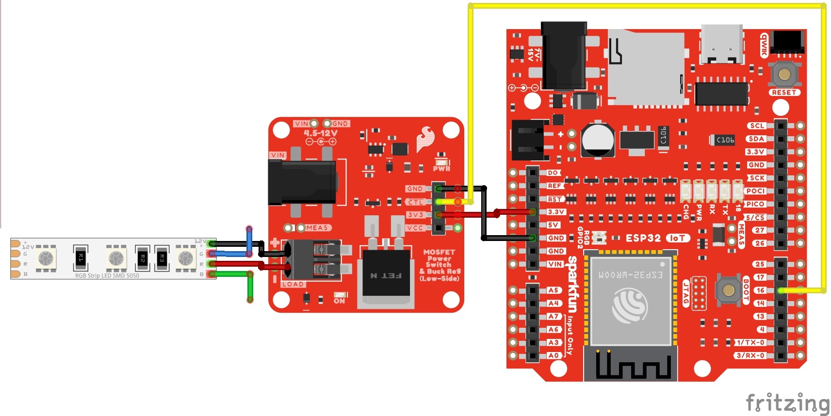
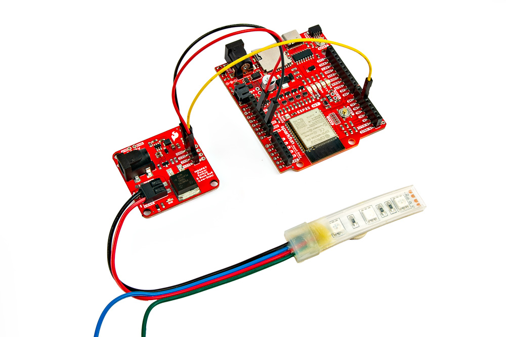
Your setup should look similar to the image below without the power supply.
Upload Code
To upload code, insert the USB cable into the IoT RedBoard - ESP32.
Copy the following code and paste it in the Arduino IDE. If you have not already, select your Board (in this case, the SparkFun ESP32 IoT RedBoard), and associated COM port. Then hit the upload button.
/******************************************************************************
  Example: Fading
  Modified By: Ho Yun "Bobby" Chan
  SparkFun Electronics
  Date: October 27th, 2023
  License: MIT. See license file for more information but you can
  basically do whatever you want with this code.

  This example is based on Arduino's fade example. It has been modified
  so that it can be used for the SparkFun IoT RedBoard- ESP32 but it can be
  used with any Arduino that has a PWM pin. The load (DC motor,
  or 12V LED) will slowly turn on and off. This code will be more useful for
  users connecting a DC motor or nonaddressable LED so that you can partially
  turn on/off the load.

  Users can also open the Serial Monitor at 115200 to check on
  the status of the button for debugging.

  Feel like supporting open source hardware?
  Buy a board or component from SparkFun!

      SparkFun MOSFET Power Switch and Buck Regulator (Low-Side): https://www.sparkfun.com/products/23979
      SparkFun IoT RedBoard - ESP32 Development Board: https://www.sparkfun.com/products/19177
      Hobby Motor - Gear: https://www.sparkfun.com/products/11696
      Blower - Squirrel Cage (12V): https://www.sparkfun.com/products/11270
      12V LED RGB Strip - Bare (1m): https://www.sparkfun.com/products/12021
      Wall Adapter 12V/600mA, (Barrel Jack): https://www.sparkfun.com/products/15313

  Distributed as-is; no warranty is given.
******************************************************************************/

int loadPin = 16;

// the setup function runs once when you press reset or power the board
void setup() {

//Initialize Serial for Debugging if there is no built-in LED
Serial.begin(115200);
Serial.println("Analog fade in and out to slowly turn on/off load!");

// Set up the load pin to be an output and turn it off:
pinMode(loadPin, OUTPUT);
analogWrite(loadPin, 255);

Serial.println("OFF");

}  //END SETUP

// the loop function runs over and over again forever
void loop() {

Serial.println("<===== FADE IN =====>");
// fade in from min to max in increments of 5 points:
for (int fadeValue = 255; fadeValue >= 0; fadeValue -= 5) {
// sets the value (range from 0 to 255):
analogWrite(loadPin, fadeValue);
// wait for 30 milliseconds to see the dimming effect
delay(30);

Serial.println(fadeValue);
}

Serial.println("<===== FADE OUT =====>");
// fade out from max to min in increments of 5 points:
for (int fadeValue = 0; fadeValue <= 255; fadeValue += 5) {
// sets the value (range from 0 to 255):
analogWrite(loadPin, fadeValue);
// wait for 30 milliseconds to see the dimming effect
delay(30);

Serial.println(fadeValue);
}

}  //END LOOP
What You Should See
Once the code has uploaded, disconnect the USB cable from the IoT RedBoard - ESP32. Then insert the barrel jack from a power supply to the MOSFET Power Switch and Buck Regulator's barrel jack connector. In this case, we used a 12V wall adapter power supply.
The load will slowly turn on and slowly turn off. This will loop forever until power is removed from the board. If necessary, disconnect the 3.3V jumper wire from the IoT RedBoard - ESP32, reconnect the USB cable, and open the Arduino Serial Monitor at 115200 baud for debugging purposes.
While this example was used to turn on one channel of a 12V RGB LED strip, you could also use this example with a DC motor. Try using a potentiometer (or any 3.3V analog sensor) with the map() function to adjust the speed of the motor.
12V RGB LED Strip
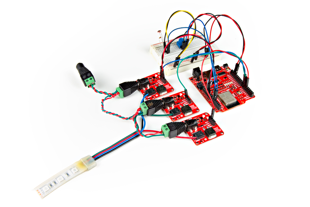
In this example, we will control all three channels of the RGB LED strip. Since we've already hooked up a 12V RGB LED strip before, we will also a circuit with a potentiometer to cycle between each color and a photoresistor to turn on the LEDs whenever the light is below a certain light level. The following example code is based on the SparkFun Inventor's Kit v4.1 Night Light example.
Non-Addressable RGB LED Strip Hookup Guide
SparkFun Inventor's Kit Experiment Guide - v4.1
Parts Needed
Grab the following quantities of each part listed to build this circuit:
- 1x SparkFun IoT RedBoard - ESP32 Development Board
- 1x USB-C Cable
- 3x SparkFun MOSFET Power Switch and Buck Regulator (Low-Side)
- 1x SparkFun Mini Screwdriver
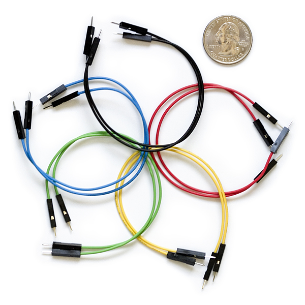
- 19x M/M Jumper Wires*
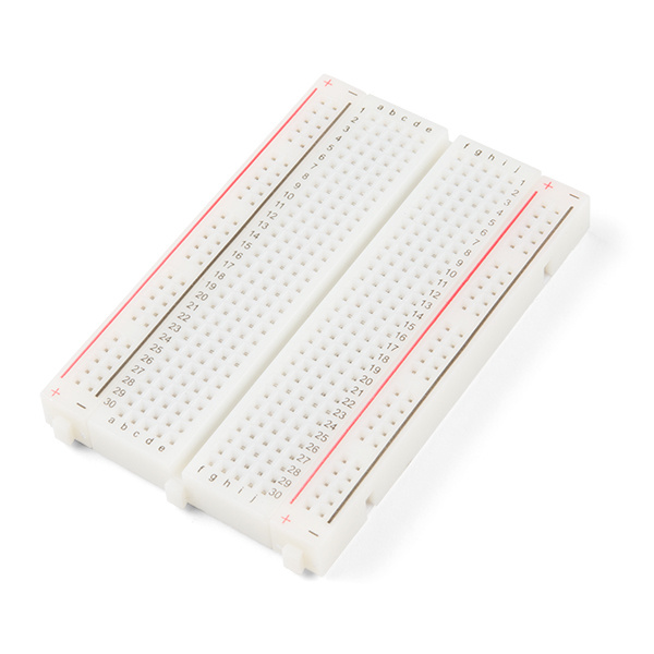
- 1x Breadboard
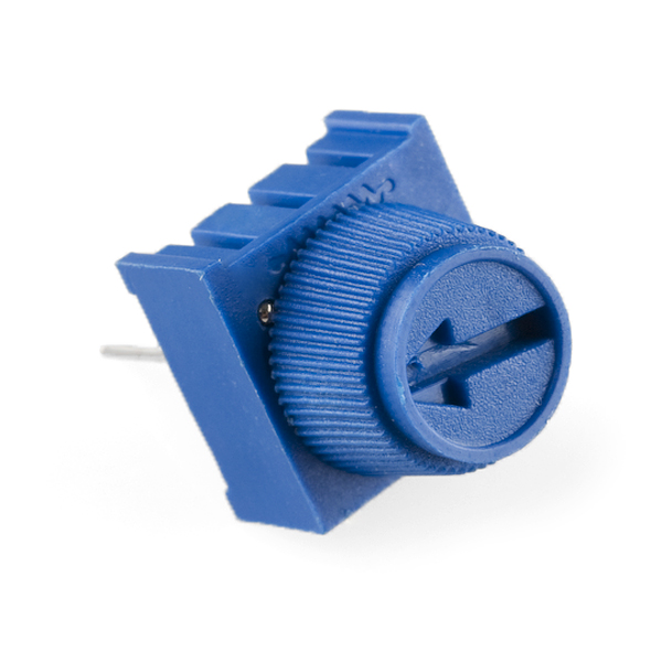
- 1x 10kΩ Potentiometer with Knob
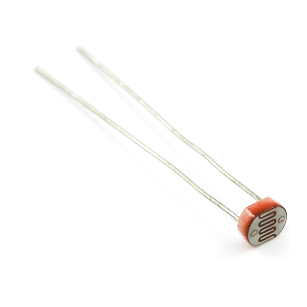
- 1x Mini Photocell
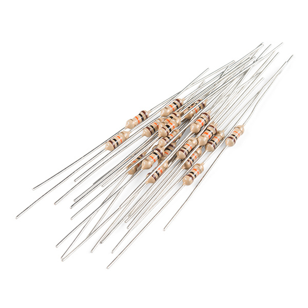
- 1x 10kΩ Resistor
- 1x 12V RGB LED Strip
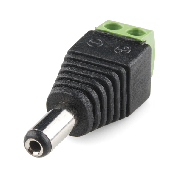
- 1x DC Barrel Jack Adapter - Male
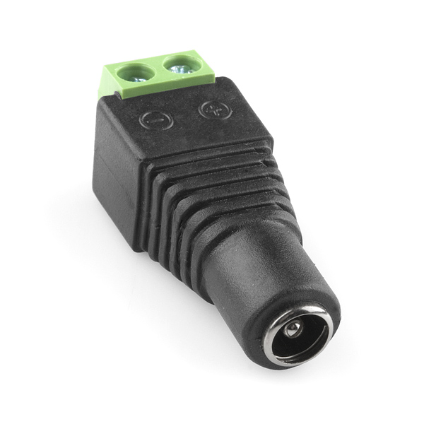
- 3x DC Barrel Jack Adapter - Female
- 1x 12V Wall Adapter
Hardware Hookup
For this particular example, we will use three channels from a 12V RGB LED strip while also including a similar circuit from the SparkFun Inventor's Kit v4.1. The circuit diagram is shown below.
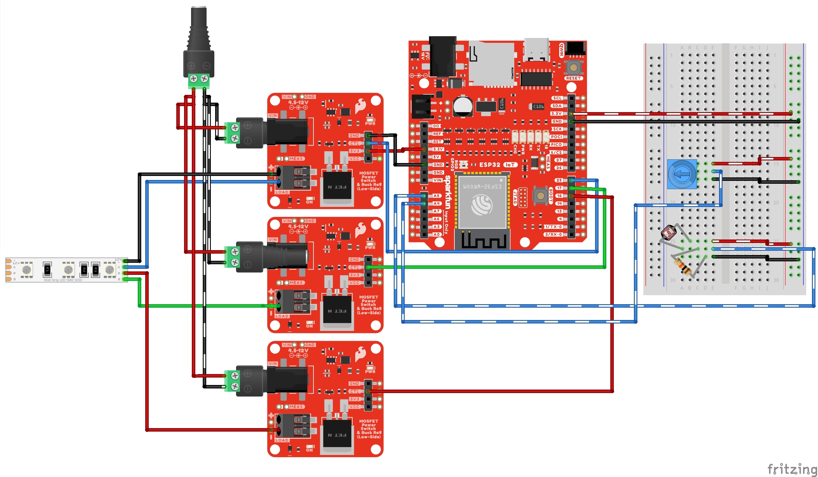
Keep in mind that instead of the RedBoard with ATmega328P, we are using the IoT RedBoard with ESP32. Since the hardware is different, the following code was modified:
- analog and PWM pins were redefined in the example code
- threshold was modified due to the ADC's higher resolution
- logic is reversed due to the transistors
Your setup should look similar to the image below without the power supply.
Upload Code
To upload code, insert the USB cable into the IoT RedBoard - ESP32.
Copy the following code and paste it in the Arduino IDE. If you have not already, select your Board (in this case, the SparkFun ESP32 IoT RedBoard), and associated COM port. Then hit the upload button.
/*
12V RGB LED Nightlight Example

Turns an 12V RGB strip LED on or off based on the light level read by a photoresistor.
Change colors by turning the potentiometer. This example is based off the SparkFun
Inventor's Kit v4.2 RGB Night-Light Example:

  https://learn.sparkfun.com/tutorials/sparkfun-inventors-kit-experiment-guide---v41

Note that instead of the RedBoard with ATmega328P, we are using the IoT RedBoard with ESP32.
Since the hardware is different, the following code was modified:

  - analog and PWM pins were redifined
  - threshold was modified due to the ADC's higher resolution
  - logic is reversed due to the transistors

WARNING: Since the IoT RedBoard with ESP32 has a system voltage of 3.3V, the logic levels
is 3.3V instead of 5V on the RedBoard with ATmega328P. Thus, the analog reference voltage
for the potentiometer and photoresistor is 3.3V. Make sure you are using 3.3V!

This sketch was written by SparkFun Electronics, with lots of help from the Arduino community.
This code is completely free for any use.

*/

int photoresistor = A4;          //variable for storing the photoresistor value
int potentiometer = A5;          //this variable will hold a value based on the position of the knob
int threshold = 3000;            //if the photoresistor reading is lower than this value the light will turn on
                             /*Note: The ESP32's ADC resolution is bigger. The max is 4095. In a bright room
                             with your finger covering the sensor, the threshold was about 3000. In a dimly
                             lit room, the threshold was about 1000. You will need to adjust this value when
                             installing it in a room. Just make sure to make it a little more than the thresholed
                             of the room. Try adding a button and some code  to save the threshold value! */

//LEDs are connected to these pins
int RedPin = 16;
int GreenPin = 17;
int BluePin = 25;

void setup() {
Serial.begin(115200);           //start a serial connection with the computer
Serial.println("12V RGB LED Strip Nightlight!");

//set the LED pins to output
pinMode(RedPin, OUTPUT);
pinMode(GreenPin, OUTPUT);
pinMode(BluePin, OUTPUT);

} //END SETUP

void loop() {

photoresistor = analogRead(A4);         //read the value of the photoresistor
potentiometer = analogRead(A5);         //read the value of the potentiometer

Serial.print("Photoresistor value:");
Serial.print(photoresistor);          //print the photoresistor value to the serial monitor
Serial.print("  Potentiometer value:");
Serial.println(potentiometer);          //print the potentiometer value to the serial monitor

if (photoresistor < threshold) {        //if it's dark (the photoresistor value is below the threshold) turn the LED on
//These nested if statements check for a variety of ranges and
//call different functions based on the current potentiometer value.
//Those functions are found at the bottom of the sketch.

/*Note: We divided 4095 by 7 colors and had a window of about 585. For users
        Adding more colors, try dividing 4095 by the total number and adjust
        eac condition statement*/

if (potentiometer > 0 && potentiometer <= 585)
  red();
if (potentiometer > 585 && potentiometer <= 1170)
  orange();
if (potentiometer > 1170 && potentiometer <= 1755)
  yellow();
if (potentiometer > 1755 && potentiometer <= 2340)
  green();
if (potentiometer > 2340 && potentiometer <= 2925)
  cyan();
if (potentiometer > 2925 && potentiometer <= 3510)
  blue();
if (potentiometer > 3510)
  magenta();
}
else {                                //if it isn't dark turn the LED off

turnOff();                            //call the turn off function

}

delay(100);                             //short delay so that the printout is easier to read

} //END LOOP

void red () {

//set the LED pins to values that make red
analogWrite(RedPin, 0);
analogWrite(GreenPin, 255);
analogWrite(BluePin, 255);
}
void orange () {

//set the LED pins to values that make orange
analogWrite(RedPin, 0);
analogWrite(GreenPin, 128);
analogWrite(BluePin, 255);
}
void yellow () {

//set the LED pins to values that make yellow
analogWrite(RedPin, 0);
analogWrite(GreenPin, 0);
analogWrite(BluePin, 255);
}
void green () {

//set the LED pins to values that make green
analogWrite(RedPin, 255);
analogWrite(GreenPin, 0);
analogWrite(BluePin, 255);
}
void cyan () {

//set the LED pins to values that make cyan
analogWrite(RedPin, 255);
analogWrite(GreenPin, 0);
analogWrite(BluePin, 0);
}
void blue () {

//set the LED pins to values that make blue
analogWrite(RedPin, 255);
analogWrite(GreenPin, 255);
analogWrite(BluePin, 0);
}
void magenta () {

//set the LED pins to values that make magenta
analogWrite(RedPin, 0);
analogWrite(GreenPin, 255);
analogWrite(BluePin, 0);
}
void turnOff () {

//set all three LED pins to 0 or OFF
analogWrite(RedPin, 255);
analogWrite(GreenPin, 255);
analogWrite(BluePin, 255);
}
What You Should See
Once the code has uploaded, disconnect the USB cable from the IoT RedBoard - ESP32. Then insert the barrel jack from a power supply to the MOSFET Power Switch and Buck Regulator's barrel jack connector. In this case, we used a 12V wall adapter power supply.
The MOSFET Power Switch & Buck Regulator with the wall adapter. Cover the photoresistor with your finger (or just turn off the lights in the room) and turn the potentiometer. You should notice the colors cycling through as the potentiometer is within certain ranges. You will probably want to disconnect the 3.3V jumper wire from the IoT RedBoard - ESP32, reconnect the USB cable, and open the Arduino Serial Monitor at 115200 baud for debugging purposes. That way you can view the serial data and adjust the threshold value based on the lighting in the room.
Now that we have ported the example from the RedBoard Qwiic with an ATmega328P to the RedBoard IoT Development Board - ESP32, try adjusting the condition statement with the potentiometer to add additional colors. Or even writing some code save the threshold value whenever a button is pressed down. You can also try to take advantage of the ESP32's wireless capabilities and adjust the color of the LED strip based on the weather.
Going Further and Other Resources
There are more examples in the Arduino Library that allow you to control a Squirrel Cage Blower to make a little "magic," as well. Feel free to check them out!
Suggested Reading
If you aren’t familiar with the the preceding concepts, we recommend checking out these tutorials to gain a little background knowledge.