$19.95
The ESP8266 is a cost-effective, and very capable WiFi-enabled microcontroller. Like any microcontroller, it can be programmed to blink LEDs, trigger relays, monitor sensors, or automate coffee makers, and with an integrated WiFi controller, the ESP8266 is a one-stop shop for almost any Internet-connected project. To top it all off, the ESP8266 is incredibly easy-to-use: firmware can be developed in Arduino and uploaded over a simple, serial interface.
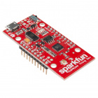
To take advantage of all of those benefits, we've created the ESP8266 Thing Development Board -- an ESP8266 development board, with an integrated FTDI USB-to-Serial chip.
The ESP8266 Thing Development Board breaks out all of the module's pins, and the USB-to-serial converter means you don't need any peripheral components to program the chip. Just plug in a USB cable, download the Arduino board definitions, and start IoT-ing.
This tutorial will help you get your ESP8266 Thing Development Board from zero to Internet-controlled blinking. It's split into the following sections:
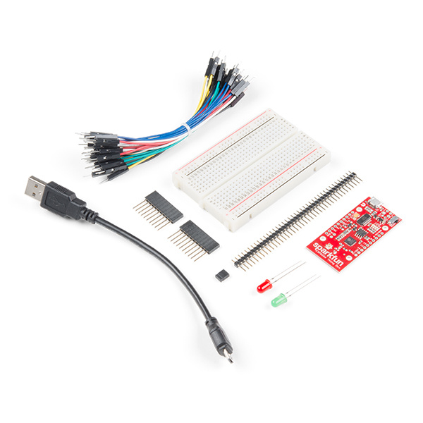
If you are ordering the ESP8266 Thing Development individually, you will need a few components to get started. Beyond the ESP8266 Thing Development Board itself, all you should need to get started is a micro-B USB Cable, which will deliver power the board and set up our USB programming interface.
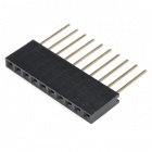
Depending on how you want to use the board, you may also want to add male headers, female headers, or hedge your bets with 10-pin stackable headers.
Before continuing on with this tutorial, you may want to familiarize yourself with some of these topics if they're unfamiliar to you:
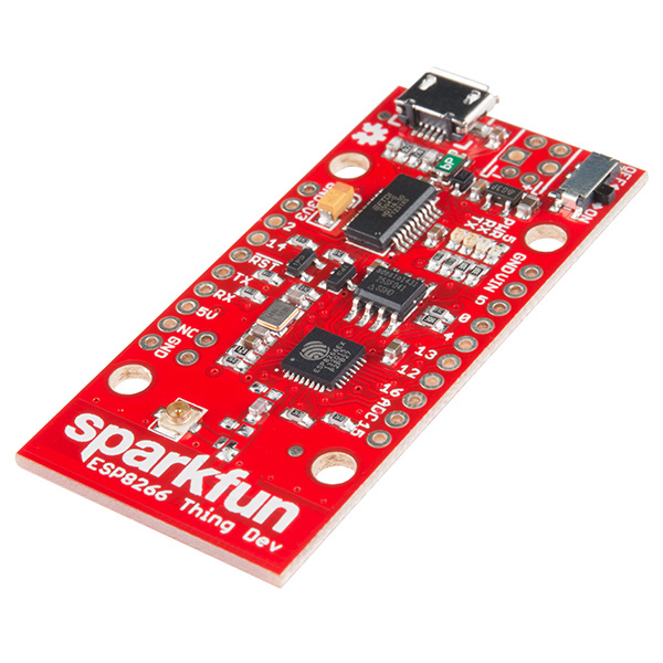
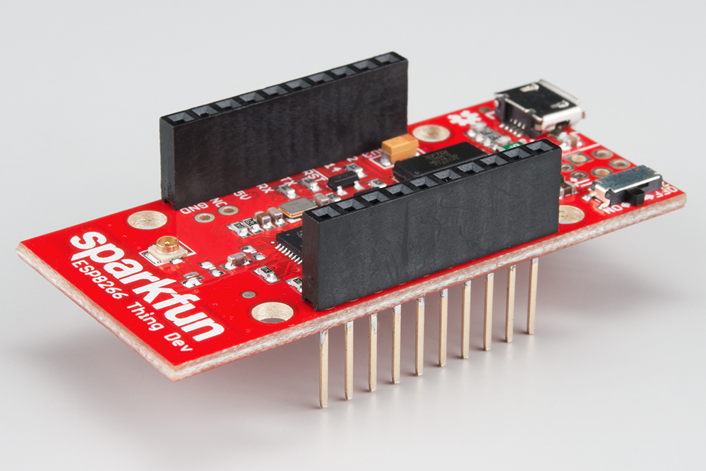
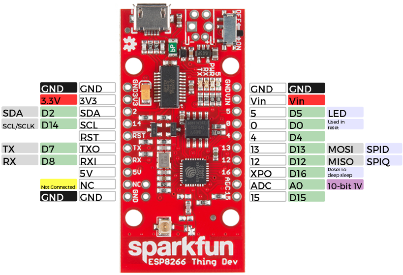
The ESP8266 Thing Development Board is a relatively simple board. The pins are broken out to two parallel, breadboard-compatible rows. The USB connector sits next to an optional power supply input, and an ON/OFF switch -- controlling power to the ESP8266 -- sits next to that. And LEDs towards the inside of the board indicate power, charge, and status of the IC.
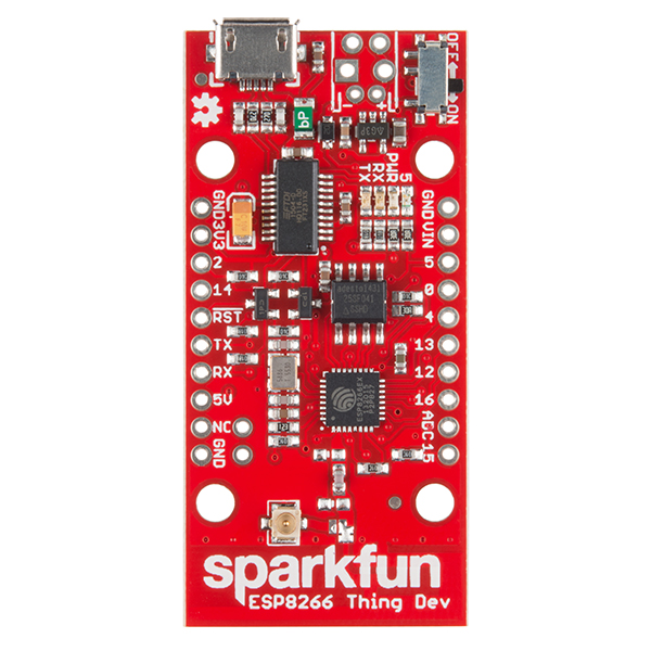
This section provides a quick overview of the Thing Dev Board's main components.
The header on the left provides an interface for serial, I2C, and power:
| Pin Label | ESP8266 I/O Function(s) | Notes |
|---|---|---|
| GND | Ground (0V). | |
| 3V3 | 3.3V | |
| 2 | GPIO2, SDA | Can either be used as ESP8266 GPIO2 or I2C serial data (SDA). |
| 14 | GPIO14, SCL, SCLK | Can either be used as ESP8266 GPIO14 or I2C serial clock (SCL). Also used as the SPI clock (SCLK). |
| RST | The ESP8266's active-low reset input. The board includes a 10kΩ pull-up resistor on this pin. | |
| TX | GPIO7, TX1 | ESP8266 UART1 data output. |
| RX | GPIO8, RX1 | ESP8266 UART1 data input. |
| 5V | USB supply output. If USB is connected, this pin will supply about 4.8V. | |
| NC | Not connected to anything. | |
| GND | Ground (0V). |
The top portion of this header breaks out the ESP8266's I2C interface, a popular interface for a variety of sensors including motion sensor, light sensor, digital-to-analog converter, or OLED display, I2C is often the protocol of choice.
If you need the extra I/O, instead of I2C, the SDA and SCL pins can be used as GPIO 2 and 14 respectively. The SCL pin also serves as the clock (SCLK) for the ESP8266's SPI interface.
The lower part of the header breaks out one of the ESP8266's serial UARTs. This serial port is used to program the thing, so be careful using it for other tasks.
The rest of the power, control, and I/O pins are broken out on the other side of the board. They are:
| Pin Label | ESP8266 I/O Function | Notes |
|---|---|---|
| GND | Ground (0V). | |
| VIN | USB connected: ~5V output Can alternatively be used as a voltage supply input to the 3.3V regulator. | |
| 5 | GPIO5 | This pin is also tied to the on-board LED. |
| 0 | GPIO0 | |
| 4 | GPIO4 | |
| 13 | GPIO13, MOSI | Hardware SPI MOSI |
| 12 | GPIO12, MISO | Hardware SPI MISO |
| 16 | GPIO16, XPD | Can be connected to reset to wake the ESP8266 from deep sleep mode. |
| ADC | A0 | A 10-bit ADC with a maximum voltage of 1V. |
| 15 | GPIO15 |
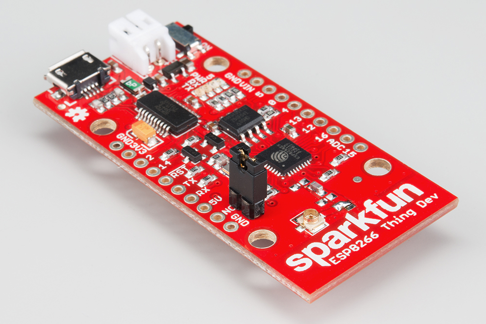
If your project requires a power source other than USB, the Thing Dev Board includes footprints for a 2-pin JST, 2-pin 3.5mm screw terminal, or a simple 0.1"-pitch 2-pin header.

You can supply anywhere between 3.3V and 6V into these inputs to power the board.
A pair of jumpers on the back of the board can be used to help reduce the Thing's power consumption.
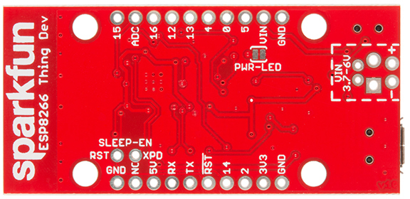
| Jumper Label | Default Setting | Notes |
|---|---|---|
| SLEEP-EN | Open | Connects GPIO16 (XPD) to the ESP8266's RST pin. |
| PWR-LED | Closed | Completes the power LED indicator circuit. |
The SLEEP-EN jumper connects GPIO16 (which has the XPD functionality) to the ESP8266's reset input. This connection is required if you want the ESP8266 to automatically wake itself from deep sleep.
To use the jumper solder a 2-pin male header and slide a 2-pin jumper on and off. This is a through-hole jumper only, because you'll need to remove the jumper to program the ESP2866.
The PWR-LED jumper allows you to disable the power LED. The LED will normally pull about 7mA, which is a ton compared to the ESP8266's 10's of µA consumption in sleep mode.
To disable the power LED, slice the interconnecting trace with your handy hobby knife.
The Thing Dev Board's default WiFi antenna is a PCB trace antenna based on this TI app note. It's cost-effective and actually works really well!
If you need to connect a more sensitive antenna, or need to route outside an enclosure, a U.FL connector is also available on the board, but isn't connected by default to the ESP8266's antenna pin. To connect this antenna to the chip, you'll need to swap the jumper by removing the solder blob and pushing it over to the other side.
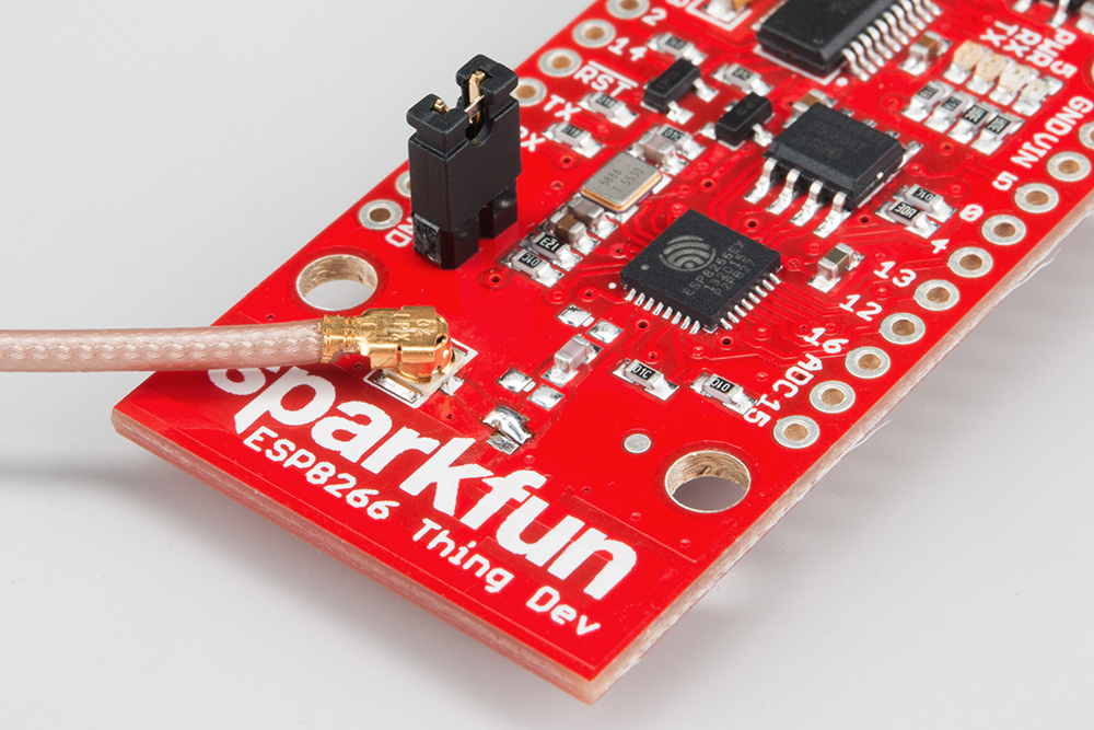
Then attach a U.FL WiFi antenna of your choice. Our adhesive antenna or a U.FL-to-RP-SMA adapter/2.4GHz Duck Antenna combo are good options.
To use any of the Thing Dev Board's GPIO pins, you'll need to solder something to the board. If you've never soldered before, this is a great time to start! These solder points are easy, through-hole pins, check out our How to Solder - Through-hole Soldering for help getting started.
What, exactly, you solder to the board depends on how you'll use it in your project. There are a variety of header options, including stackable headers, straight male headers, or straight female headers.
Stackable Headers make it convenient to both breadboard the Thing Dev Board and jumper wire out of it.
And, of course, wire can be soldered to any of the pins that have a long way to connect to something.
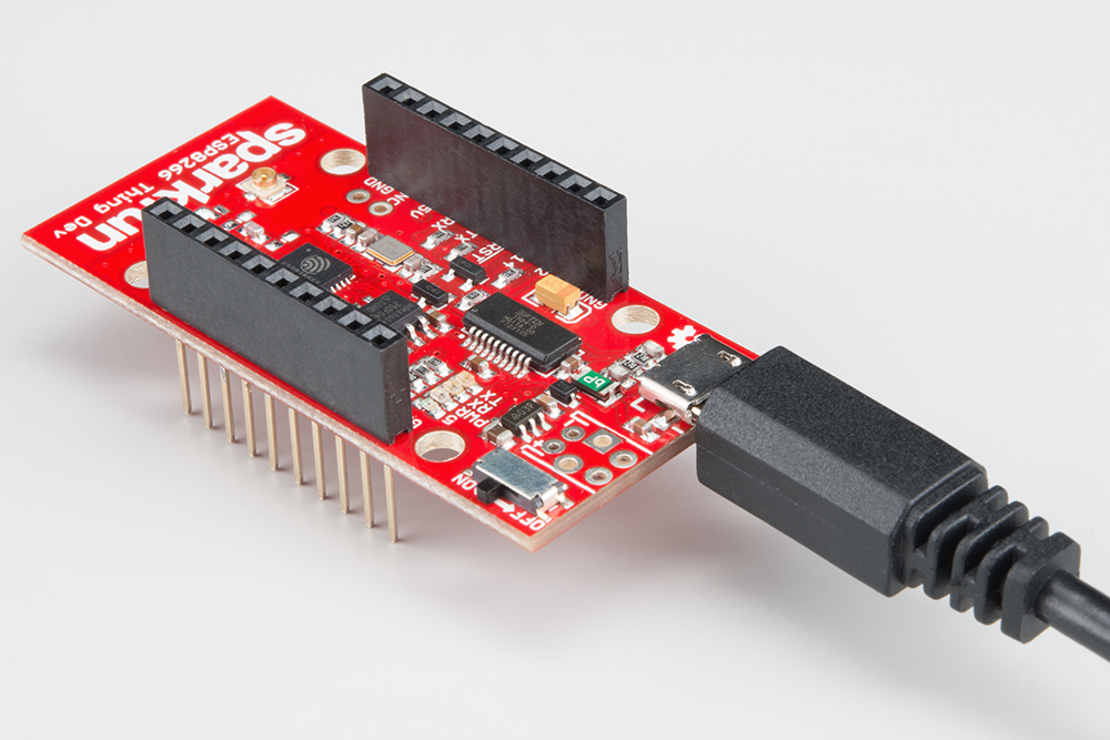
The easiest way to power the Thing Dev Board is by connecting a USB cable to the micro-B USB jack. The other end of the USB cable can be connected to your computer or a USB wall wart. After powering the board, make sure the ON/OFF switch is slid into the "ON" position, and you should see the "PWR" LED illuminate.
Alternatively, you can solder a variety of connectors into the VIN position to run the board on some other power supply. For example, you could solder a 2-pin JST connector and mate the board with a 2xAA Battery Holder to power your project.
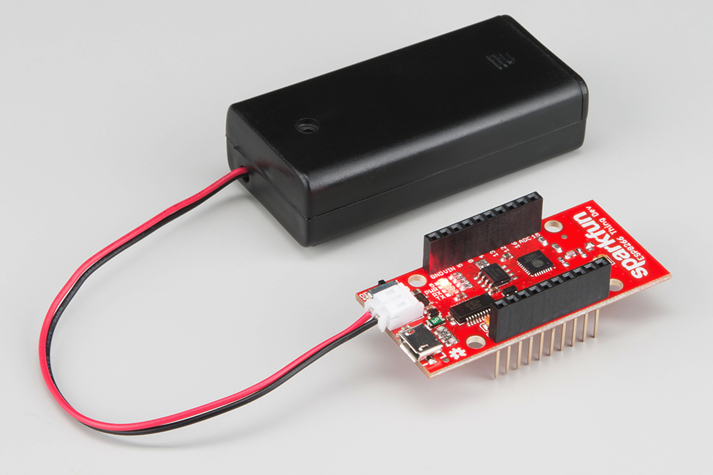
(A pair of AA batteries may slightly underpower the 3.3V regulator, but the board should still provide more than the 1.8V required for the ESP8266.)
Driver Install: If you've never used an FTDI device, you may need to install drivers on your computer before you can program the ESP8266. For help with that, follow along with our How to Install FTDI Drivers tutorial.
We have installation directions documented for all major operating systems:
There are a variety of development environments that can be equipped to program the ESP8266. You can go with a simple Notepad/gcc setup, fine-tune an Eclipse environment, or use a virtual machine provided by Espressif. If you're just getting started, though, we recommend the comfy confines of the Arduino IDE.
With the release of Arduino 1.6.4, adding third party boards to the Arduino IDE is easily achieved through the board manager. If you're running an older version of Arduino (1.6.3 or earlier), we recommend upgrading now. As always, you can download the latest version of Arduino from arduino.cc.
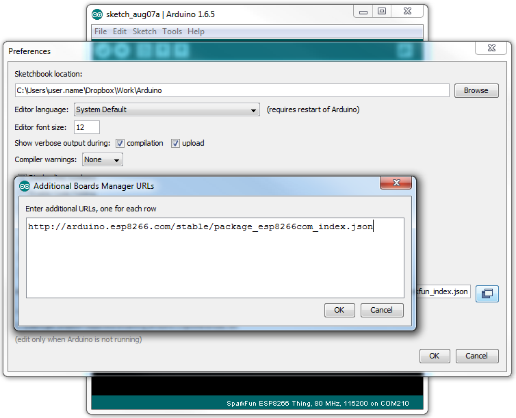
To begin, you'll need to point the Arduino IDE board manager to a custom URL. Open up Arduino, then go to the Preferences (File > Preferences). Then, towards the bottom of the window, paste this URL into the "Additional Board Manager URLs" text box:
http://arduino.esp8266.com/stable/package_esp8266com_index.json
You can add multiple URLs by clicking the window icon, and pasting in one URL per line.
Hit OK. Then navigate to the Board Manager by going to Tools > Boards > Boards Manager. Look for esp8266. Click on that entry, then select Install.
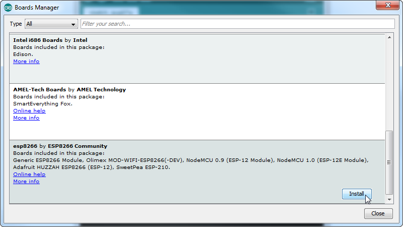
The board definitions and tools for the ESP8266 include a whole new set of gcc, g++, and other reasonably large, compiled binaries, so it may take a few minutes to download and install (the archived file is ~110MB). Once the installation has completed, an Arduino-blue "INSTALLED" will appear next to the entry.
With the Board addon installed, all that's left to do is select "SparkFun ESP8266 Thing Dev" from the Tools > Boards menu.
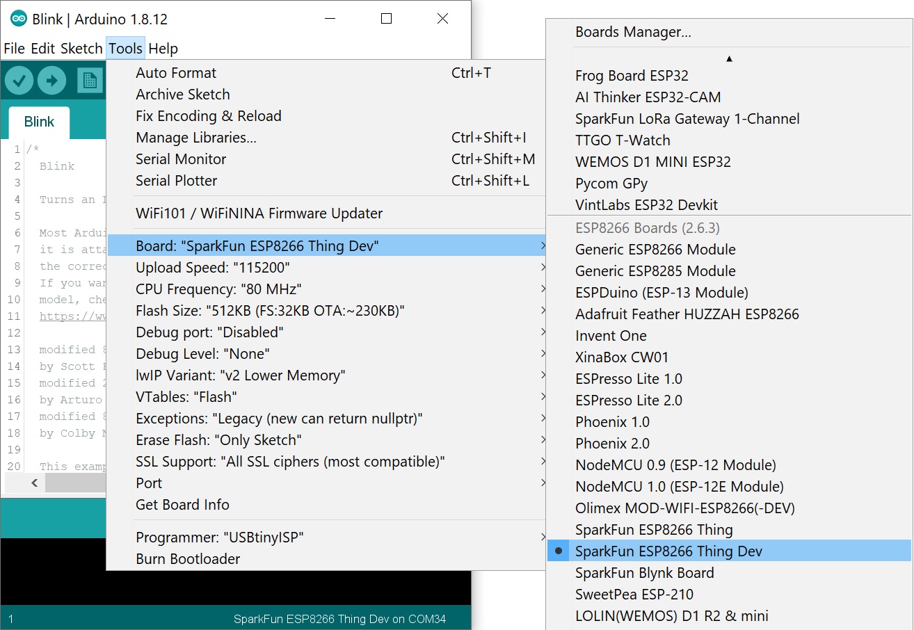
Then select your FTDI's port number under the Tools > Port menu.
To verify that everything works, try uploading the old standard: Blink. But instead of blinking pin 13, toggle pin 5, which is attached to the onboard LED.
language:c
#define ESP8266_LED 5

void setup()
{
  pinMode(ESP8266_LED, OUTPUT);
}

void loop()
{
  digitalWrite(ESP8266_LED, HIGH); // LED off
  delay(500);
  digitalWrite(ESP8266_LED, LOW); // LED on
  delay(500);
}
If you get the following error ending with something like esptool.FatalError: Failed to connect to ESP8266: Timed out waiting for packet header:
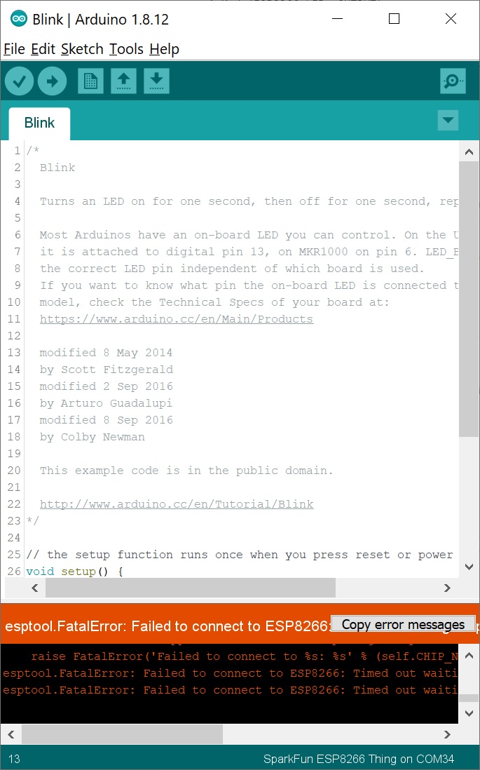
Make sure that you select the SparkFun ESP8266 Thing Dev as the board. Selecting just the "SparkFun ESP8266 Thing" without the word "Dev" can cause problems uploading when using the ESP8266 Community Board Add-On.
If every upload attempt results in an error ending with something like error: espcomm_open failed:
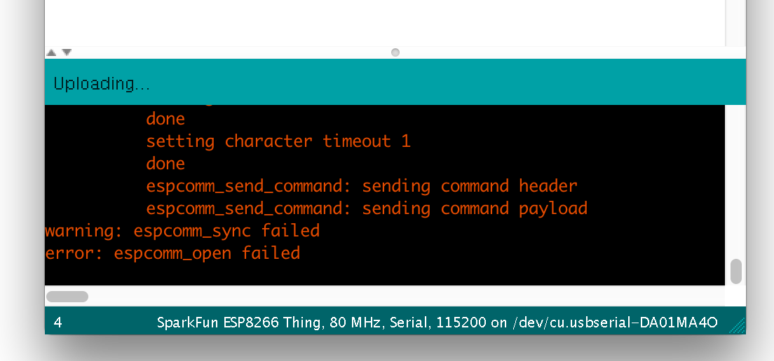
Try changing the board to Generic ESP8266 Module, and in the sub menus, make sure the following sub-menu's are also set:
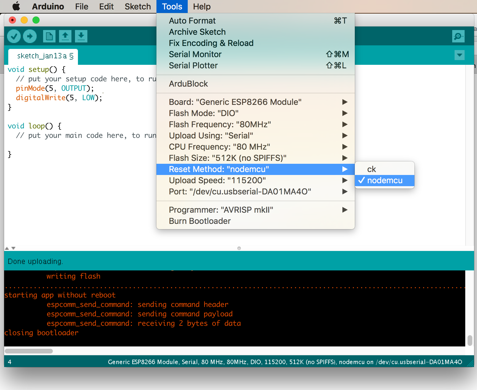
Faster Uploads! The serial upload speed defaults to 115200 bps, which is reliable, but can feel a bit slow. You can increase the upload speed by a factor of about 8 by selecting 921600 under the Tools > Upload Speed menu.
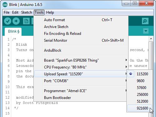
This faster upload speed can be slightly less reliable, but will save you loads of time!
There are still some bugs to be fleshed out of the esptool, sometimes it may take a couple tries to successfully upload a sketch. If you're still not having any luck uploading, try turning the board on then off, or unplug then replug the USB cable. If you still have trouble, get in touch with our amazing tech support team.
If we use the ESP8266 as a web server, you can use a web browser to control the ESP8266's LED, or read the status of its GPIO's.
This section provides two web server examples. The first example sets the ESP8266 up as a WiFi station, connecting to a WiFi router like the previous example. The other example sets the ESP8266 up as a WiFi access point, so you can use a WiFi-enabled device to connect directly to the little WiFi chip.
To begin, let's connect the Thing Dev Board back up to the WiFi access point you used in the previous example. Here's some example code setting up a web server and pointing a local mDNS domain of "thing.local" to your ESP8266. Make sure you adjust the values for WiFiSSID and WiFiPSK.
language:c
#include <ESP8266WiFi.h>
#include <ESP8266mDNS.h>

//////////////////////
// WiFi Definitions //
//////////////////////
const char WiFiSSID[] = "WiFiSSID";
const char WiFiPSK[] = "WiFiPSK";

/////////////////////
// Pin Definitions //
/////////////////////
const int LED_PIN = 5; // Thing's onboard, green LED
const int ANALOG_PIN = A0; // The only analog pin on the Thing
const int DIGITAL_PIN = 12; // Digital pin to be read

WiFiServer server(80);

void setup()
{
  initHardware();
  connectWiFi();
  server.begin();
  setupMDNS();
}

void loop()
{
  // Check if a client has connected
  WiFiClient client = server.available();
  if (!client) {
    return;
  }

  // Read the first line of the request
  String req = client.readStringUntil('\r');
  Serial.println(req);
  client.flush();

  // Match the request
  int val = -1; // We'll use 'val' to keep track of both the
                // request type (read/set) and value if set.
  if (req.indexOf("/led/0") != -1)
    val = 1; // Will write LED high
  else if (req.indexOf("/led/1") != -1)
    val = 0; // Will write LED low
  else if (req.indexOf("/read") != -1)
    val = -2; // Will print pin reads
  // Otherwise request will be invalid. We'll say as much in HTML

  // Set GPIO5 according to the request
  if (val >= 0)
    digitalWrite(LED_PIN, val);

  client.flush();

  // Prepare the response. Start with the common header:
  String s = "HTTP/1.1 200 OK\r\n";
  s += "Content-Type: text/html\r\n\r\n";
  s += "<!DOCTYPE HTML>\r\n<html>\r\n";

  /*Note: Uncomment the line below to refresh automatically
   *      for every 1 second. This is not ideal for large pages
   *      but for a simple read out, it is useful for monitoring
   *      your sensors and I/O pins. To adjust the fresh rate,
   *      adjust the value for content. For 30 seconds, simply
   *      change the value to 30.*/
  //s += "<meta http-equiv='refresh' content='1'/>\r\n";//auto refresh page

  // If we're setting the LED, print out a message saying we did
  if (val >= 0)
  {
    s += "LED is now ";
    s += (val)?"off":"on";
  }
  else if (val == -2)
  { // If we're reading pins, print out those values:
    s += "Analog Pin = ";
    s += String(analogRead(ANALOG_PIN));
    s += "<br>"; // Go to the next line.
    s += "Digital Pin 12 = ";
    s += String(digitalRead(DIGITAL_PIN));
  }
  else
  {
    s += "Invalid Request.<br> Try /led/1, /led/0, or /read.";
  }
  s += "</html>\n";

  // Send the response to the client
  client.print(s);
  delay(1);
  Serial.println("Client disonnected");

  // The client will actually be disconnected
  // when the function returns and 'client' object is detroyed
}

void connectWiFi()
{
  byte ledStatus = LOW;
  Serial.println();
  Serial.println("Connecting to: " + String(WiFiSSID));
  // Set WiFi mode to station (as opposed to AP or AP_STA)
  WiFi.mode(WIFI_STA);

  // WiFI.begin([ssid], [passkey]) initiates a WiFI connection
  // to the stated [ssid], using the [passkey] as a WPA, WPA2,
  // or WEP passphrase.
  WiFi.begin(WiFiSSID, WiFiPSK);

  // Use the WiFi.status() function to check if the ESP8266
  // is connected to a WiFi network.
  while (WiFi.status() != WL_CONNECTED)
  {
    // Blink the LED
    digitalWrite(LED_PIN, ledStatus); // Write LED high/low
    ledStatus = (ledStatus == HIGH) ? LOW : HIGH;

    // Delays allow the ESP8266 to perform critical tasks
    // defined outside of the sketch. These tasks include
    // setting up, and maintaining, a WiFi connection.
    delay(100);
    // Potentially infinite loops are generally dangerous.
    // Add delays -- allowing the processor to perform other
    // tasks -- wherever possible.
  }
  Serial.println("WiFi connected");
  Serial.println("IP address: ");
  Serial.println(WiFi.localIP());
}

void setupMDNS()
{
  // Call MDNS.begin(<domain>) to set up mDNS to point to
  // "<domain>.local"
  if (!MDNS.begin("thing"))
  {
    Serial.println("Error setting up MDNS responder!");
    while(1) {
      delay(1000);
    }
  }
  Serial.println("mDNS responder started");

}

void initHardware()
{
  Serial.begin(9600);
  pinMode(DIGITAL_PIN, INPUT_PULLUP);
  pinMode(LED_PIN, OUTPUT);
  digitalWrite(LED_PIN, HIGH);
  // Don't need to set ANALOG_PIN as input,
  // that's all it can be.
}
After uploading, find a device on the same WiFi network, and point it to one of these locations (the links below will only work if your device is on the same network):
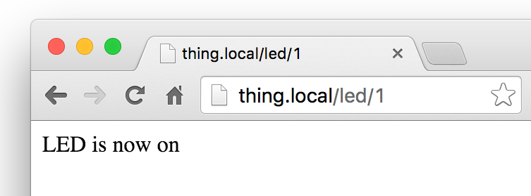
The ESP8266 should server a web page, even if it's as simple as ensuring its LED is on.
Not only can the ESP8266 connect to a WiFi network and interact with the Internet, but it can also set up a network of its own, allowing other devices to connect directly to it. This example demonstrates how to turn the ESP8266 into an access point (AP), and serve up web pages to any connected client.
Copy and paste the code from below in the Arduino IDE. Then hit the upload button.
language:c
#include <ESP8266WiFi.h>

//////////////////////
// WiFi Definitions //
//////////////////////
const char WiFiAPPSK[] = "sparkfun";

/////////////////////
// Pin Definitions //
/////////////////////
const int LED_PIN = 5; // Thing's onboard, green LED
const int ANALOG_PIN = A0; // The only analog pin on the Thing
const int DIGITAL_PIN = 12; // Digital pin to be read

WiFiServer server(80);

void setup()
{
  initHardware();
  setupWiFi();
  server.begin();
}

void loop()
{
  // Check if a client has connected
  WiFiClient client = server.available();
  if (!client) {
    return;
  }

  // Read the first line of the request
  String req = client.readStringUntil('\r');
  Serial.println(req);
  client.flush();

  // Match the request
  int val = -1; // We'll use 'val' to keep track of both the
                // request type (read/set) and value if set.
  if (req.indexOf("/led/0") != -1)
    val = 1; // Will write LED high
  else if (req.indexOf("/led/1") != -1)
    val = 0; // Will write LED low
  else if (req.indexOf("/read") != -1)
    val = -2; // Will print pin reads
  // Otherwise request will be invalid. We'll say as much in HTML

  // Set GPIO5 according to the request
  if (val >= 0)
    digitalWrite(LED_PIN, val);

  client.flush();

  // Prepare the response. Start with the common header:
  String s = "HTTP/1.1 200 OK\r\n";
  s += "Content-Type: text/html\r\n\r\n";
  s += "<!DOCTYPE HTML>\r\n<html>\r\n";

  /*Note: Uncomment the line below to refresh automatically
   *      for every 1 second. This is not ideal for large pages
   *      but for a simple read out, it is useful for monitoring
   *      your sensors and I/O pins. To adjust the fresh rate,
   *      adjust the value for content. For 30 seconds, simply
   *      change the value to 30.*/
  //s += "<meta http-equiv='refresh' content='1'/>\r\n";//auto refresh page

  // If we're setting the LED, print out a message saying we did
  if (val >= 0)
  {
    s += "LED is now ";
    s += (val)?"off":"on";
  }
  else if (val == -2)
  { // If we're reading pins, print out those values:
    s += "Analog Pin = ";
    s += String(analogRead(ANALOG_PIN));
    s += "<br>"; // Go to the next line.
    s += "Digital Pin 12 = ";
    s += String(digitalRead(DIGITAL_PIN));
  }
  else
  {
    s += "Invalid Request.<br> Try /led/1, /led/0, or /read.";
  }
  s += "</html>\n";

  // Send the response to the client
  client.print(s);
  delay(1);
  Serial.println("Client disonnected");

  // The client will actually be disconnected
  // when the function returns and 'client' object is detroyed
}

void setupWiFi()
{
  WiFi.mode(WIFI_AP);

  // Do a little work to get a unique-ish name. Append the
  // last two bytes of the MAC (HEX'd) to "ThingDev-":
  uint8_t mac[WL_MAC_ADDR_LENGTH];
  WiFi.softAPmacAddress(mac);
  String macID = String(mac[WL_MAC_ADDR_LENGTH - 2], HEX) +
                 String(mac[WL_MAC_ADDR_LENGTH - 1], HEX);
  macID.toUpperCase();
  String AP_NameString = "ThingDev-" + macID;

  char AP_NameChar[AP_NameString.length() + 1];
  memset(AP_NameChar, 0, AP_NameString.length() + 1);

  for (int i=0; i<AP_NameString.length(); i++)
    AP_NameChar[i] = AP_NameString.charAt(i);

  WiFi.softAP(AP_NameChar, WiFiAPPSK);
}

void initHardware()
{
  Serial.begin(115200);
  pinMode(DIGITAL_PIN, INPUT_PULLUP);
  pinMode(LED_PIN, OUTPUT);
  digitalWrite(LED_PIN, HIGH);
  // Don't need to set ANALOG_PIN as input,
  // that's all it can be.
}
After uploading this sketch, find another device that you can connect to a WiFi network -- phone, laptop, etc. Look for a network called "ThingDev-XXXX", where XXXX is the last 2 bytes of the Thing Development Board's MAC address.
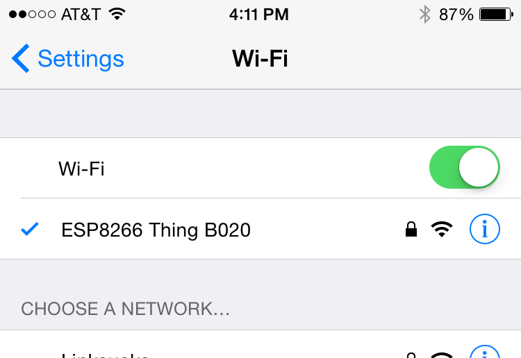
The sketch sets the network's password to "sparkfun".
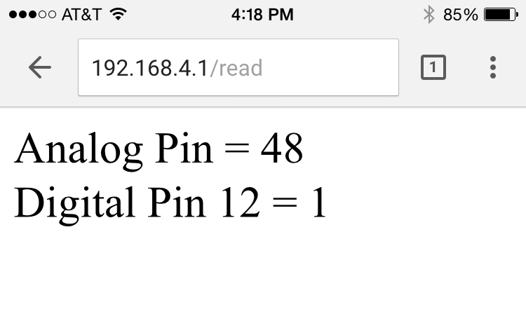
After connecting to your ESP8266's AP network, load up a browser and point it to 192.168.4.1/read (unfortunately, mDNS doesn't work in AP mode). The Thing Dev Board should serve up a web page showing you its ADC and digital pin 12 readings:
After that, give 192.168.4.1/led/0 and 192.168.4.1/led/1 a try, and keep an eye on the Thing's green LED while you do.
Tired of hitting the refresh button to update the I/O pin readings? Try uncommenting the line of code where it says: s += "<meta http-equiv='refresh' content='1'/>\r\n";. Then reupload the code to your ESP8266. This line of code will auto refresh the page every second.
language:c
  /*Note: Uncomment the line below to refresh automatically
   *      for every 1 second. This is not ideal for large pages
   *      but for a simple read out, it is useful for monitoring
   *      your sensors and I/O pins. To adjust the fresh rate,
   *      adjust the value for content. For 30 seconds, simply
   *      change the value to 30.*/
  //s += "<meta http-equiv='refresh' content='1'/>\r\n";//auto refresh page
As always, check through the code comments to get a line-by-line breakdown of what's going on.
The previous example is great for showing the nuts-and-bolts behind using HTTP to toggle outputs or read inputs. But if you're looking for a much simpler solution, we recommend checking out Blynk.
Blynk is a smartphone application that allows you to easily create "apps" that interact with Internet-connected hardware. It works with a wide variety of hardware platforms, including the Photon, Raspberry Pi, Arduino/Ethernet Shield, and, of course, the ESP8266. Here's a quick how-to on Blynk:
The Blynk app is available for both iOS and Android devices. Click one of the buttons below to get started downloading the app:
After downloading the app, create an account and log in. Welcome to Blynk!
You'll also need to install the Blynk Arduino Library, which helps generate the firmware running on your ESP8266. Download the latest release from Blynk's GitHub repo, and follow along with the directions there to install the required libraries.
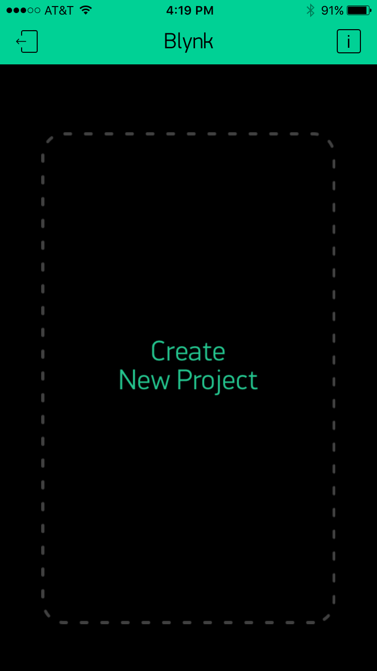
Next, click the "Create New Project" in the app to create a new Blynk app. Give it any name you please, just make sure the "Hardware Model" is set to ESP8266.
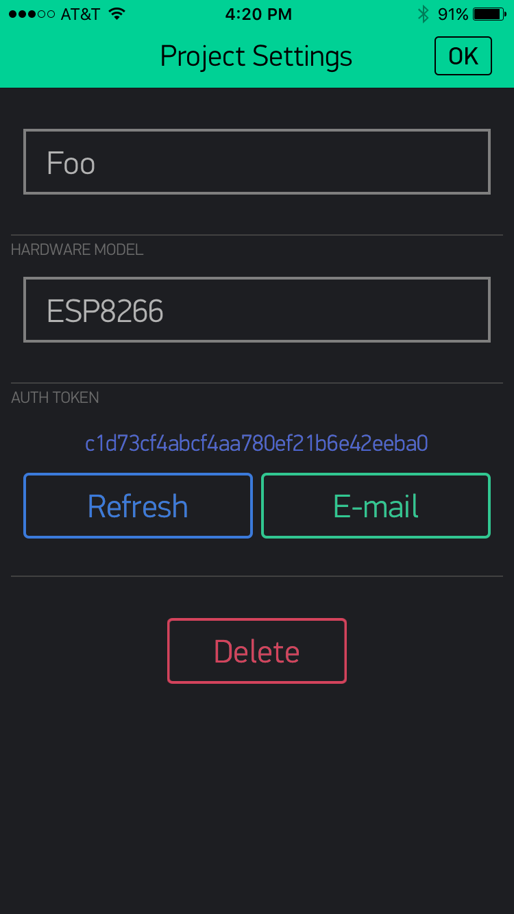
The Auth Token is very important -- you'll need to stick it into your ESP8266's firmware. For now, copy it down or use the "E-mail" button to send it to yourself.
Then you'll be presented with a blank new project. To open the widget box, click in the project window to open.
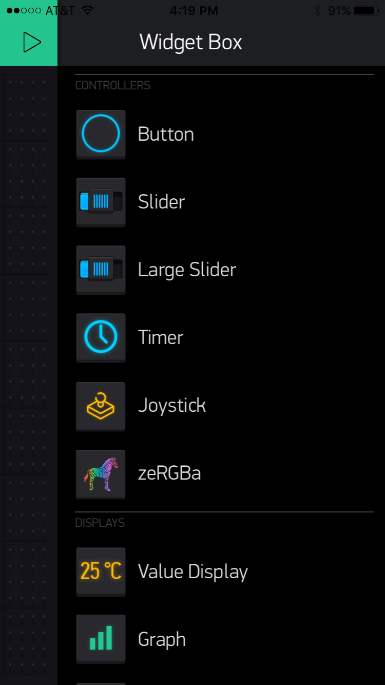
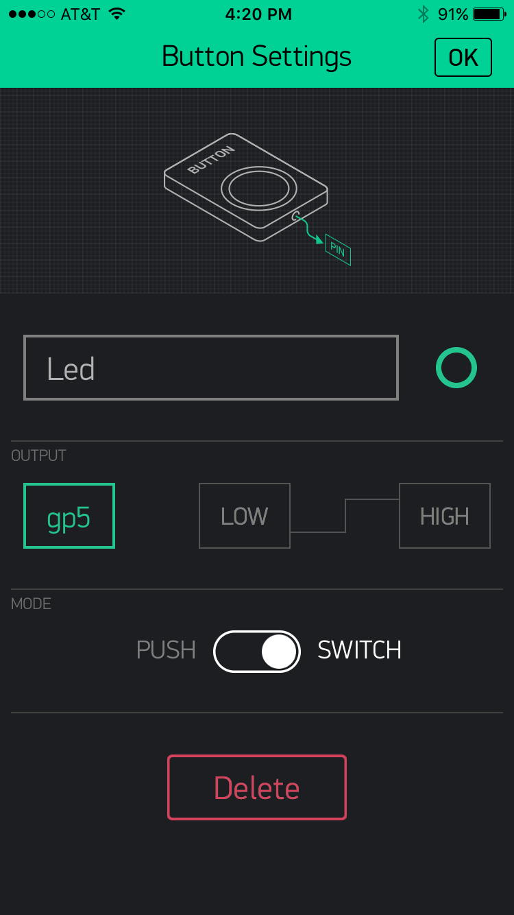
Add a Button, then click on it to change its settings. Buttons can toggle outputs on the ESP8266. Set the button's output to gp5, which is tied to an LED on the Thing Dev Board. You may also want to change the action to "Switch."
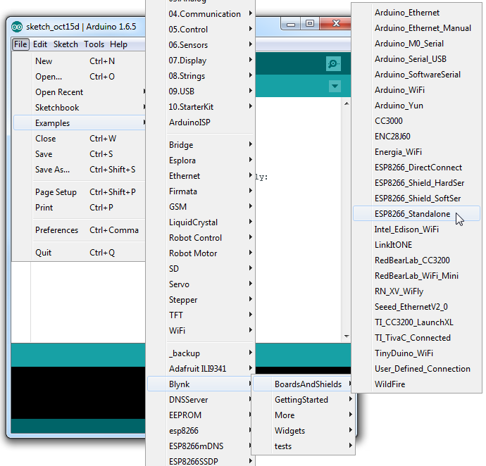
Now that your Blynk project is set up, open Arduino and navigate to the ESP8266_Standalone example in the File > Examples > Blynk > BoardsAndShields menu.
Before uploading, make sure to paste your authoriazation token into the auth[] variable. Also make sure to load your WiFi network settings into the Blynk.begin(auth, "ssid", "pass") function.
Then upload!
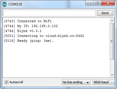
After the app has uploaded, open the serial monitor, setting the baud rate to 9600. Wait for the "Ready (ping: xms)." message.
Then click the "Run" button in the top right corner of the Blynk app. Press the button and watch the LED!
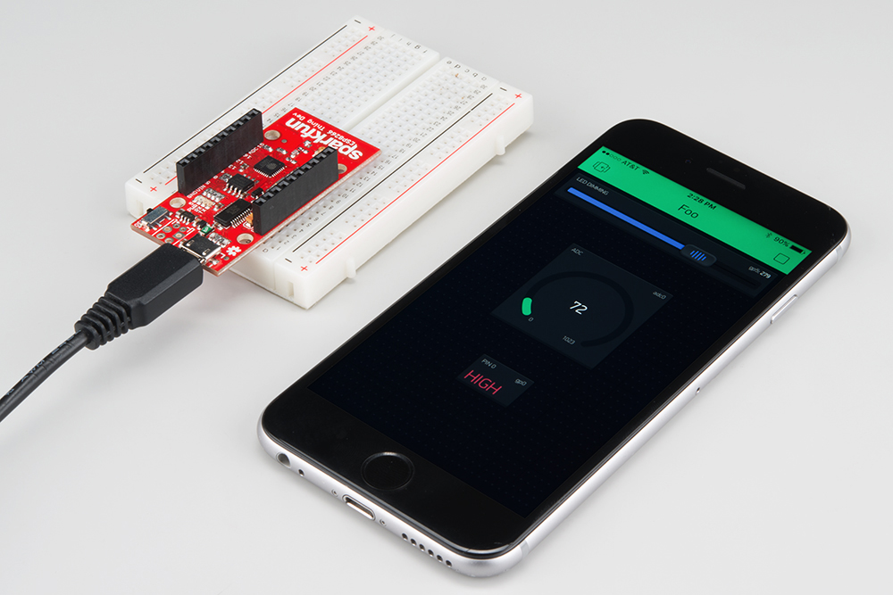
Then add more widgets to the project. They should immediately work on the ESP8266 without uploading any new firmware.
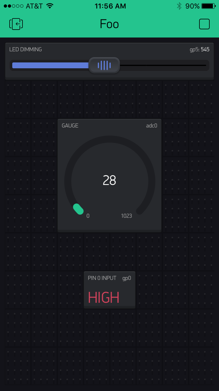
You can add analog output sliders, digital input monitors, and analog input gauges.
If you've used Arduino in the past, there will be some new programming schemes to get used to in ESP8266 land. Here are a few of the most common gotchyas. For a more comprehensive reference, check out the ESP8266 Arduino Reference page.
As with any other Arduino, the pin mappings printed on the board match the pin you read or write to. The TX and RX pins can be referenced as 7 and 8 respectively.
There's only one analog input pin, labeled ADC. To read the ADC pin, make a function call to analogRead(A0). Remember that this pin has a weird maximum voltage of 1V -- you'll get a 10-bit value (0-1023) proportional to a voltage between 0 and 1V.
All digital pins are also capable of PWM "analog" output. Use analogWrite([pin], [value]) with a value between 0 and 1023 to dim LEDs with a 1kHz PWM signal.
This is one of the most critical differences between the ESP8266 and a classic Arduino microcontroller. The ESP8266 runs a lot of utility functions in the background -- keeping WiFi connected, managing the TCP/IP stack, and performing other duties -- blocking these functions from running can cause the ESP8266 to crash and reset itself. To avoid these mysterious resets, avoid long, blocking loops in your sketch.
If you have a long loop in your sketch, you can add a delay([milliseconds]) call within, to allow the critical background functions to execute. The ESP8266's delay() funciton, while of course delaying for a set number of milliseconds, also makes a quick call to the background functions.
The ESP8266 Arduino libraries also implement a yield() function, which calls on the background functions to allow them to do their thing. As an example, if your sketch is waiting for someone to press a button attached to pin 12, creating a loop like this will keep the ESP8266 from crashing:
language:c
pinMode(12, INPUT_PULLUP); // Set pin 12 as an input w/ pull-up
while (digitalRead(12) == HIGH) // While pin 12 is HIGH (not activated)
    yield(); // Do (almost) nothing -- yield to allow ESP8266 background functions
Serial.println("Button is pressed!"); // Print button pressed message.
This is the ESP8266, so the WiFi class will probably be included in just about every sketch there is. If you've used the Arduino WiFi library before, the ESP8266 WiFi library will be very similar, there's just a few key differences:
#include <ESP8266WiFi.h> not <WiFi.h>.WiFi.begin(NetworkSSID, NetworkPassword). You can also set the ESP8266 up as a WiFi access point by calling WiFi.softAP(AP_SSID, AP_Password).WiFi.setMode([mode]) with either WIFI_AP, WIFI_STA, or WIFI_STA_AP as the parameter.The examples earlier in this tutorial should have demonstrated all of these differences.
A lot of the core Arduino libraries have been re-written to work for the ESP8266, including:
Wire.begin() will assume pins 2 and 14 are SDA and SCL, but you can manually set them to any other pin by calling Wire.begin([SDA], [SCL]).SPI.setFrequency([frequency]) -- is added. You may need to call that in your setup to slow the clock down from its default value. For example, SPI.setFrequency(1000000) will set the SPI clock to 1MHz.| Pin Number | SPI Function |
|---|---|
| 12 | MISO |
| 13 | MOSI |
| 14 (SCL) | SCLK |
| 15 | CS |
The ESP8266 has a pretty decent low-power sleep mode -- operating around 70µA. To put the ESP8266 to sleep, use the ESP.deepSleep(<microseconds>) function.
language:c
ESP.deepSleep(30000000); // Sleep 30 seconds
For it to wake itself back up, the ESP8266 requires an external connection between pin 16 and its RST pin. Use the handy "Sleep-EN" jumper to set this connection up.
Now that you've successfully got your ESP8266 Thing Development Board up and running, it's time to incorporate it into your own project! For more information, check out the resources below:
An astoundingly awesome community has grown around the ESP8266. We owe them big time for the amazing Arduino addon they've cooperatively built. For all of your ESP8266 needs, we recommend checking out the esp8266.com Community Forum. In addition to that, here are a few ESP8266-related resources we've found incredibly helpful:
Need a little project inspiration, now that you've got your ESP8266 Thing up-and-running? With its deep sleep ability, the Thing is a great foundation for a WiFi-based weather station, a friendly, huggable, interactive plushy. Maybe some of these related SparkFun tutorials will help spur some ideas.
Or check out SparkFun's project spotlight on the SparkFun Rogue Router for a Solar Powered File Server with the ESP8266:
Or check out some of these blog posts for ideas:
learn.sparkfun.com | CC BY-SA 3.0 | SparkFun Electronics | Niwot, Colorado