Environmental Monitoring with the Tessel 2
 rwaldron
Build It
Let's begin by assembling the environment monitoring device!
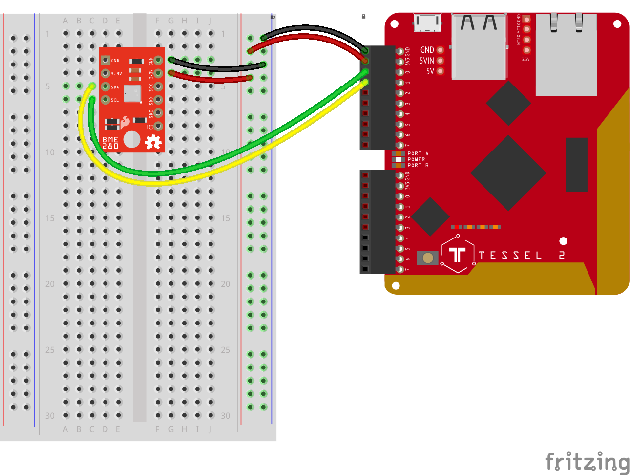
Start by plugging the BME280 into the breadboard so that it straddles the DIP support ravine (notch) that runs vertically down the middle of the breadboard. Next, connect the BME280 to the Tessel 2 with jumper wires as shown in the wiring diagram:
| BME280 | Tessel 2 |
|---|---|
| GND | GND |
| 3.3V | 3.3V |
| SCL | Port A, Pin 0 |
| SDA | Port A, Pin 1 |
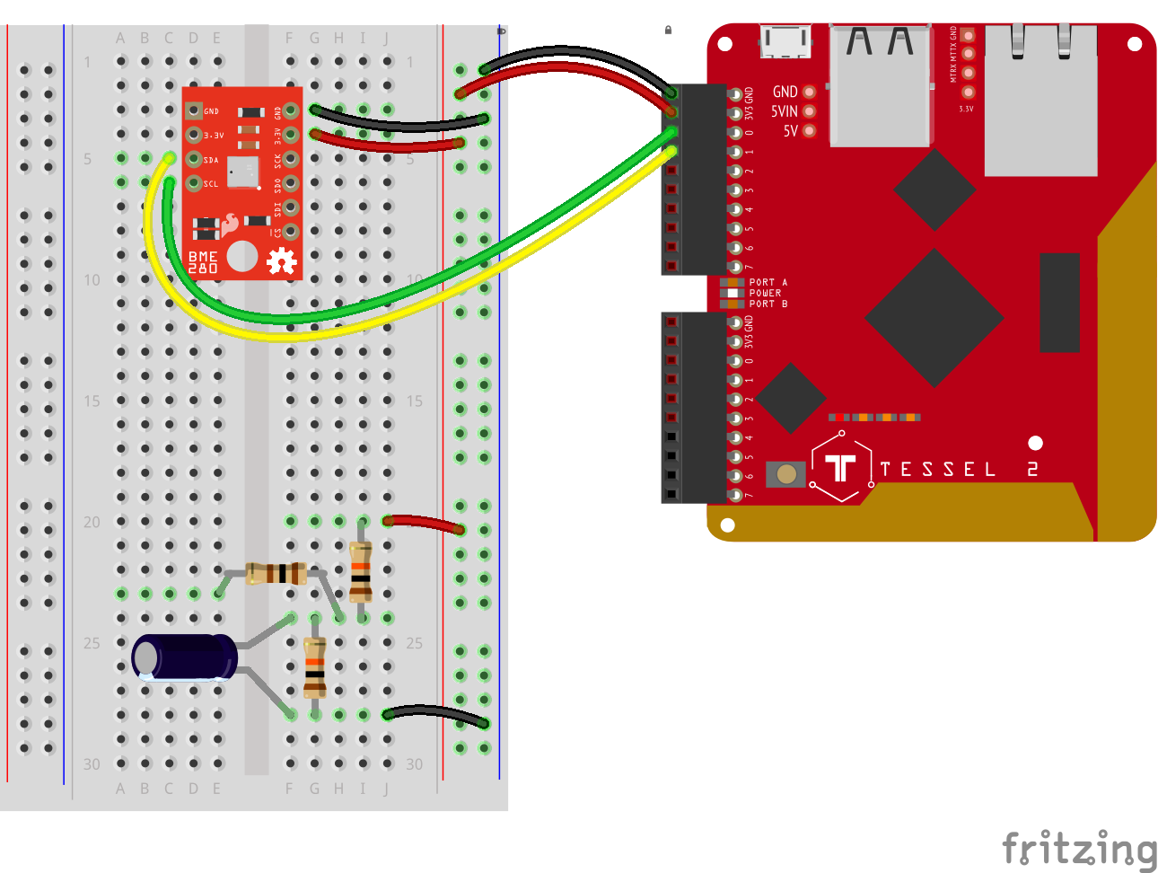
Add the current sensor's voltage divider circuit.
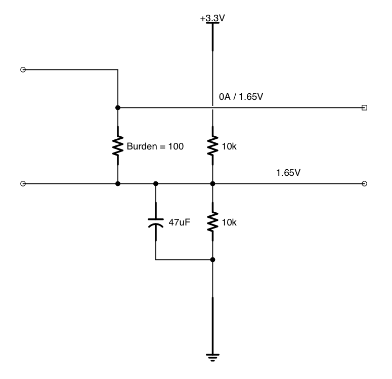
Here's a closer look at the voltage divider circuit:
This voltage divider circuit "conditions" the output of the current sensor so that it is constrained to a range of input voltages that can be read by the Tessel 2 (0 - 3.3V). If you'd like to learn more about the technical details, you can read about the circuit it is based on, described in the article CT [Current Transformer] Sensors — Interfacing with an Arduino, OpenEnergyMonitor.org.
The final circuit should look like this:

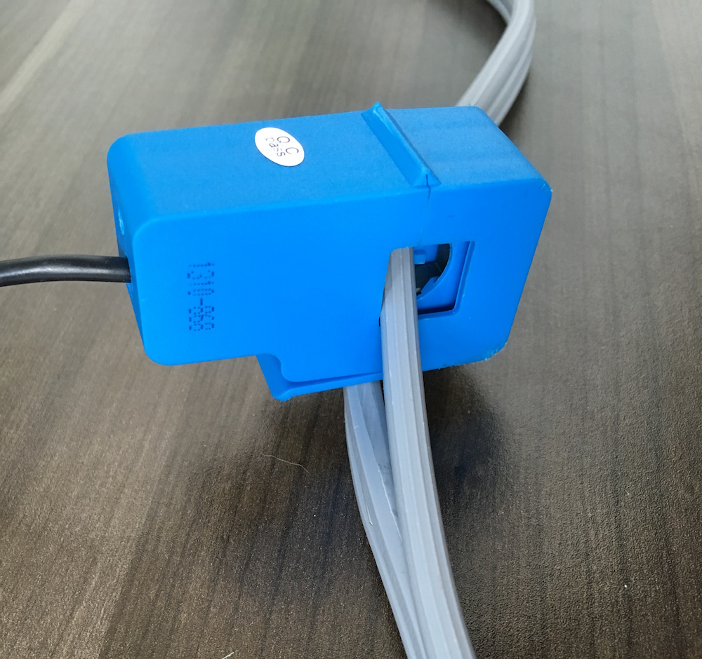
Next, you'll need a sharp utility knife and a safe, clean cutting surface. On your surface, lay the Air Conditioner Extension Cord flat, and use the utility knife to separate one of the three joined sections of wire. Make the cut approximately 3 to 4 inches long—just long enough to put the current sensor's top "jaw" through and safely clip it together.