Electret Mic Breakout Board Hookup Guide
Example Circuit and Code
We are going to run through a very simple project to get you started lighting an LED on the RedBoard based on the ADC values picked up by your microcontroller.
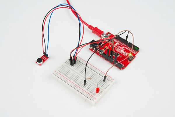
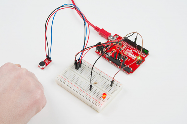
This is the Knocker. An LED will light up when a knock is detected.
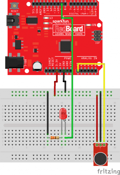
Make the Following Connections
Electret Mic BOB → RedBoard
- VCC → 3.3V
- GND → GND
- AUD → A0 (or any analog pin)
- LED+ → digital Pin 9
- LED- → GND
Note: This example assumes you are using the latest version of the Arduino IDE on your desktop. If this is your first time using Arduino, please review our tutorial on installing the Arduino IDE.
If you have not previously installed an Arduino library, please check out our installation guide.Open the Arduino IDE and create a new project.
language:c
 /*
 * The Circuit:
 * Connect AUD to analog input 0
 * Connect GND to GND
 * Connect VCC to 3.3V (3.3V yields the best results)
 *
 *  To adjust when the LED turns on based on audio input:
 *  Open up the serial com port (Top right hand corner of the Arduino IDE)
 *  It looks like a magnifying glass. Perform several experiments
 *  clapping, snapping, blowing, door slamming, knocking etc and see where the
 *  resting noise level is and where the loud noises are. Adjust the if statement
 *  according to your findings.
 *
 *  You can also adjust how long you take samples for by updating the "SampleWindow"
 *
 * This code has been adapted from the
 * Example Sound Level Sketch for the
 * Adafruit Microphone Amplifier
 *
 */

const int sampleWindow = 250; // Sample window width in mS (250 mS = 4Hz)
unsigned int knock;
int ledPin = 9;

void setup()
{
   Serial.begin(9600);
  pinMode(ledPin, OUTPUT);
}

void loop()
{
 unsigned long start= millis();  // Start of sample window
 unsigned int peakToPeak = 0;   // peak-to-peak level

 unsigned int signalMax = 0;
 unsigned int signalMin = 1024;

 // collect data for 250 miliseconds
 while (millis() - start < sampleWindow)
 {
   knock = analogRead(0);
      if (knock < 1024)  //This is the max of the 10-bit ADC so this loop will include all readings
      {
         if (knock > signalMax)
         {
           signalMax = knock;  // save just the max levels
         }
      else if (knock < signalMin)
        {
         signalMin = knock;  // save just the min levels
         }
     }
 }
 peakToPeak = signalMax - signalMin;  // max - min = peak-peak amplitude
 double volts = (peakToPeak * 3.3) / 1024;  // convert to volts


Serial.println(volts);
 if (volts >=1.0)
 {
  //turn on LED
  digitalWrite(ledPin, HIGH);
   delay(500);
  Serial.println("Knock Knock");
 }
 else
 {
 //turn LED off
 digitalWrite(ledPin, LOW);
 }
}
Once you have loaded and run the program with your hardware hooked up, you should the LED attached to pin 9 on the RedBoard light up when you knock. Check out the WindBag Alert that uses the same code with just a few additional lines for an additional practice and project inspiration.


