Electret Mic Breakout Board Hookup Guide
Introduction
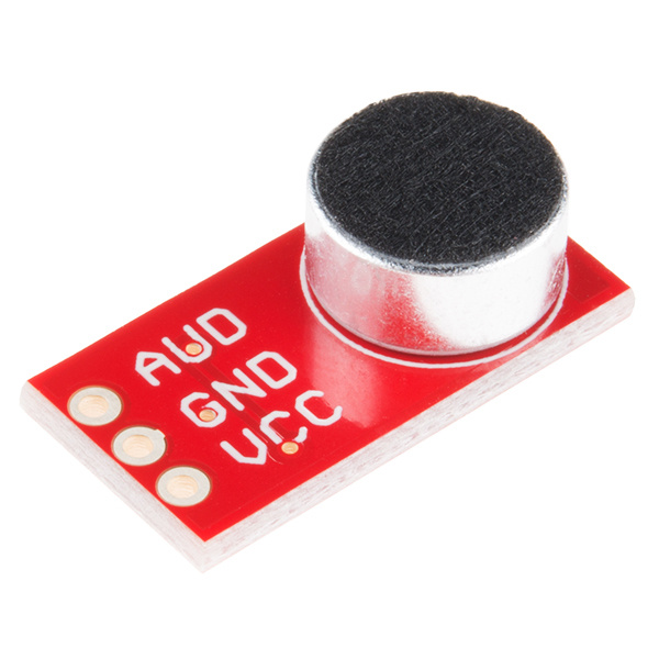
Ready to add audio to your next project? The SparkFun Electret Microphone Breakout couples an Electret microphone (100Hz - 10kHz) with a 60x mic preamplifier to amplify the sounds of voice, claps, door knocks or any sounds loud enough to be picked up by a microcontroller’s analog to digital converter.
The Electret Mic Breakout translates amplitude (not volume) by capturing sound waves between two conducting plates (one a vibrating diaphragm and the other fixed) in the microphone and converting them into electrical waves. These electrical signals are then amplified and picked up by your microcontroller's ADC. In this tutorial, we will present two different projects to get you up and running with your next sound reactive project in a snap or a clap.
Materials Required
For this tutorial you will only need a few tools and components.
Recommended Reading
If you are not familiar or comfortable with the following concepts, we recommend reading through these before continuing on with the Electret Mic BOB Hookup Guide.
How to Use a Breadboard
What is an Arduino?
Analog vs. Digital
Hardware Overview
Hardware
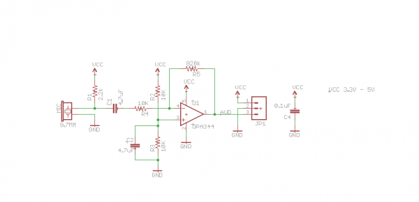
The Electret Mic Breakout Board only has three pins: VCC, GND and AUD. You can power this device from 3.3V to 5V, so it is a great compliment to most microcontroller units. For the amplification, we used Texas Instruments OPA344 rail-to-rail precision amplifier to give you maximum output swing.
Schematic
The gain of the amplifier is set by R5/R4 which is approximately 82V/V. Simulation and testing puts the gain closer to 60V/V.
Frequency Response
What this tells you is that you will see the same gain across the frequency spectrum that is picked up by the mic (100Hz-10KHz). The input of the amplifier is biased at 1/2 VCC. The very small AC voltage output by the mic rides on the DC offset and gets amplified through the OPA344. The output from the "AUD" pin is also at 1/2 the supply voltage, so it can be connected directly to the ADC of microcontroller. In quiet conditions, the ADC will ideally read 1/2 the full scale or 512 on a 10-bit converter.
Example Circuit and Code
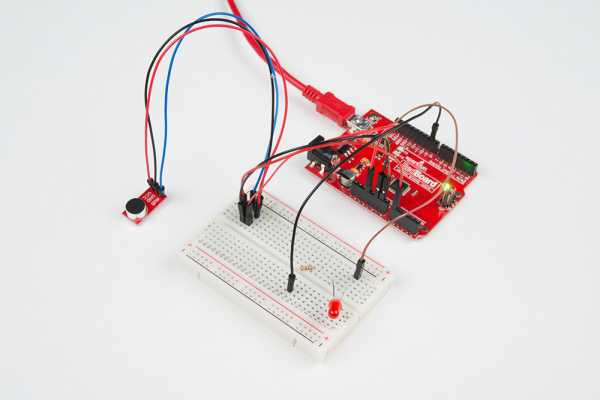
We are going to run through a very simple project to get you started lighting an LED on the RedBoard based on the ADC values picked up by your microcontroller.
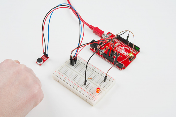
This is the Knocker. An LED will light up when a knock is detected.
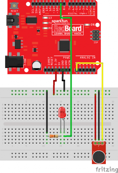
Make the Following Connections
Electret Mic BOB → RedBoard
- VCC → 3.3V
- GND → GND
- AUD → A0 (or any analog pin)
- LED+ → digital Pin 9
- LED- → GND
Note: This example assumes you are using the latest version of the Arduino IDE on your desktop. If this is your first time using Arduino, please review our tutorial on installing the Arduino IDE.
If you have not previously installed an Arduino library, please check out our installation guide.Open the Arduino IDE and create a new project.
language:c
 /*
 * The Circuit:
 * Connect AUD to analog input 0
 * Connect GND to GND
 * Connect VCC to 3.3V (3.3V yields the best results)
 *
 *  To adjust when the LED turns on based on audio input:
 *  Open up the serial com port (Top right hand corner of the Arduino IDE)
 *  It looks like a magnifying glass. Perform several experiments
 *  clapping, snapping, blowing, door slamming, knocking etc and see where the
 *  resting noise level is and where the loud noises are. Adjust the if statement
 *  according to your findings.
 *
 *  You can also adjust how long you take samples for by updating the "SampleWindow"
 *
 * This code has been adapted from the
 * Example Sound Level Sketch for the
 * Adafruit Microphone Amplifier
 *
 */

const int sampleWindow = 250; // Sample window width in mS (250 mS = 4Hz)
unsigned int knock;
int ledPin = 9;

void setup()
{
   Serial.begin(9600);
  pinMode(ledPin, OUTPUT);
}

void loop()
{
 unsigned long start= millis();  // Start of sample window
 unsigned int peakToPeak = 0;   // peak-to-peak level

 unsigned int signalMax = 0;
 unsigned int signalMin = 1024;

 // collect data for 250 miliseconds
 while (millis() - start < sampleWindow)
 {
   knock = analogRead(0);
      if (knock < 1024)  //This is the max of the 10-bit ADC so this loop will include all readings
      {
         if (knock > signalMax)
         {
           signalMax = knock;  // save just the max levels
         }
      else if (knock < signalMin)
        {
         signalMin = knock;  // save just the min levels
         }
     }
 }
 peakToPeak = signalMax - signalMin;  // max - min = peak-peak amplitude
 double volts = (peakToPeak * 3.3) / 1024;  // convert to volts


Serial.println(volts);
 if (volts >=1.0)
 {
  //turn on LED
  digitalWrite(ledPin, HIGH);
   delay(500);
  Serial.println("Knock Knock");
 }
 else
 {
 //turn LED off
 digitalWrite(ledPin, LOW);
 }
}
Once you have loaded and run the program with your hardware hooked up, you should the LED attached to pin 9 on the RedBoard light up when you knock. Check out the WindBag Alert that uses the same code with just a few additional lines for an additional practice and project inspiration.
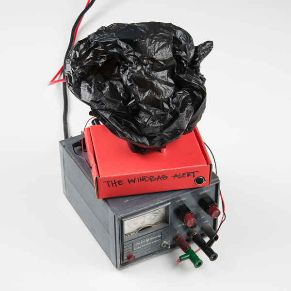
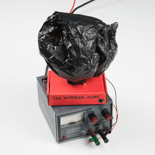
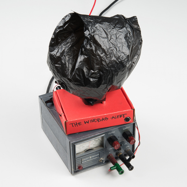
The Windbag Alert
Do you have a co-worker that talks too much? Do you want to alert that long-talker in your life of their offenses with the least unassuming desk ornament? Do you like literal translations of bad expressions? Then make yourself a Windbag Alert. This rude little piece of hardware will inflate a bag (one of my doggy doop-doop bags) with the air of your stolen silence.
Here the bag is deflated but the Electret Mic is listening. If ADC values are above a certain threshold for too long the bag will begin to inflate.
Here, someone has been talking for about 30 seconds. They have just a few seconds before the bag fully inflates. The fan kicking on usually stops them dead in their tracks.
But, some people, those people, don't care. And the bag completely inflates. Alerting that person they are indeed the office Windbag.
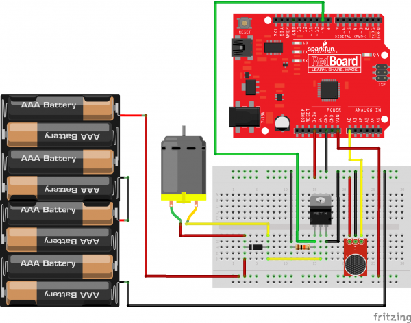
Let's break this thing down. This project is simply a continuation for the LED Blinking project from the previous section.
Hardware
I used a 12V computer fan, because that's what I had laying around. You can use any fan, even disassemble a hand held cooling fan found at dollar stores.
I used an old SparkFun box as my project enclosure, which sits on my power supply on my workbench. I wrapped a plastic bag around the computer fan using electrical tape. There is about 1/2" of space between the box top and fan. I used standoffs there. Make sure there is enough air flow.
Software
language:c
const int sampleWindow = 250; // Sample window width in mS (250 mS = 4Hz)
unsigned int sample;
int Wind = 9;

void setup()
{
  Serial.begin(9600);
  pinMode(Wind, OUTPUT);
}

void loop()
{
unsigned long startMillis= millis();  // Start of sample window
unsigned int peakToPeak = 0;   // peak-to-peak level

unsigned int signalMax = 0;
unsigned int signalMin = 1024;

// collect data for 1 second
while (millis() - startMillis < sampleWindow)
{
      sample = analogRead(0);
    if (sample < 1024)  //This is the max of the 10-bit ADC so this loop will include all readings
    {
         if (sample > signalMax)
        {
            signalMax = sample;  // save just the max levels
         }
         else if (sample < signalMin)
         {
            signalMin = sample;  // save just the min levels
         }
      }
   }
  peakToPeak = signalMax - signalMin;  // max - min = peak-peak amplitude
 double volts = (peakToPeak * 3.3) / 1024;  // convert to volts


Serial.println(volts);
if (volts >=0.5)
{
    //turn on FAN
    digitalWrite(Wind, HIGH);
delay(1000);
  digitalWrite(Wind, LOW);
delay(75);
  digitalWrite(Wind, HIGH);
delay(75);
  digitalWrite(Wind, LOW);
delay(75);
  digitalWrite(Wind, HIGH);
delay(75);
  digitalWrite(Wind, LOW);
delay(75);
  digitalWrite(Wind, HIGH);
delay(75);
   }
  else
  {
  //turn FAN off
 digitalWrite(Wind, LOW);
 }
}
I suggest playing with the delays so you can finely tune your machine to suit your needs.
Fin the Electret Blimp
I came across this project on Instructables while researching Soft Robotics and fell in love with the simplicity and the affect it has with those who connect with it. Pritika Nilaratna developed this socially awkward autonomous blimp to interact and vie for your attention. I made one and will be sharing how to create your own adorable electronic dirigible. I made this project using her platform but created the code based on the servo code used in the SparkFun Inventor's Kit, so, if you have the SIK, you are pretty much ready to make your own sound reactive floating thingy. Please share your projects with an Attribution-ShareAlike 3.0 Unported License.
Parts Needed for Blimp:
You will also need hot glue, clear packing tape, helium (found a tank at a party supply store) and a soldering iron to put this together.
Hardware
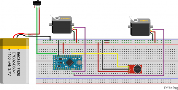
The hardware is pretty simple. The wires connecting the battery to the switch, the switch to the Pro Mini, and the Electret Mic to the Pro Mini should be as short as possible. The wires from the servos to the Pro Mini need to be about a foot long. Using wire wrapping wire makes getting multiple connections in one spot much easier, and it's lighter. I taped the battery to the back of the Pro Mini and taped the Electret Mic to the front. Eventually, I will make a little top hat to hold all the electronics and go to tea with Fin in his fancy new hat.
I recommend prototyping this on a bread board first and figuring out which motor is left and which is right. Dry fitting everything first will also help you use the right amount wire so you don't short yourself.
Software
Use the code below to program Fin.
language:c
//Fin the Electret Blimp is the original creation of
//Pritika Nilaratna
//Ollie is Licensed under the Attribution-ShareAlike 3.0 Unported License
//Please share your projects under the same license!
//Code Developed from Sparkfun SIK
//Hardware and Design adopted from Ollie


#include <Servo.h> // Servo Library
Servo servoL; //Left Servo Control Object
Servo servoR; //Right Servo control Object

//Sound variables
const int sampleWindow = 250; // Sample window width in mS (250 mS = 4Hz)
unsigned int sound;


void setup()
{
  servoL.attach(5);  // attaches the left servo on pin 5
  servoR.attach(6);  // attached the right servo on pin 6
  Serial.begin(9600); // open the serial port at 9600 bps:
 }


void loop()
{
  int position=0;
  servoL.write(0); //Set the position of Left fin
  servoR.write(0); //set the position of Right fin

  //set up sound detection
  unsigned long start= millis();  // Start of sample window
  unsigned int peakToPeak = 0;    // peak-to-peak level
  unsigned int signalMax = 0;
  unsigned int signalMin = 1024;

  // collect data for 250 miliseconds
  while (millis() - start < sampleWindow)
   {
     sound = analogRead(0);
       if (sound < 1024)  //This is the max of the 10-bit ADC so this loop will include all readings
         {
           if (sound > signalMax)
            {
              signalMax = sound;  // save just the max levels
            }
           else if (sound < signalMin)
            {
               signalMin = sound;  // save just the min levels
            }
         }
   }
  peakToPeak = signalMax - signalMin;  // max - min = peak-peak amplitude
  double volts = (peakToPeak * 3.3) / 1024;  // convert to volts
  Serial.print("Volts:");
  Serial.print("\t");
  Serial.println(volts);
  if (volts >=1.0)
   {

    //To make your Blimp seem more excited copy and paste
    // the "Up Motion" and "Down Motions" as many
    //Time as you'd like. Right now his fins will flap
    //4 times.

     Serial.println("HEY!! HELLO!!"); //Should have named it NAVI
     for (position =0; position <= 75; position +=5)//Up Motion
        {
        servoL.write(position); //move Left Fin to next position
        servoR.write(position); //move Right Fin to next position
        delay(20);
        }
      for (position = 75; position>=0; position -=5)//Down Motion
        {
         servoL.write(position); //move Left Fin to Next position
         servoR.write(position); // move Right Fin to Next position
         delay(20);
        }
      for (position =0; position <= 75; position +=5)//Up motion
        {
        servoL.write(position); //move Left Fin to next position
        servoR.write(position); //move Right Fin to next position
        delay(20);
        }
      for (position = 75; position>=0; position -=5) // Down Motion
        {
         servoL.write(position); //move Left Fin to Next position
         servoR.write(position); // move Right Fin to Next position
         delay(20);
        }
        delay(800); // This delay helps the elecret mic recover from hearing
        //the sound of the Servo motors.
    }
}

//end. Change it up and show us if you've made one and how you modified it!
Construction
Make the Wings
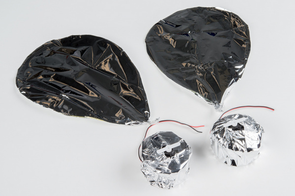
Create the form for the shape of the wings using the 16 gauge jewelry wire. It can be any shape you'd like as long as you make two of them using the same amount of wire. Remember, the weight needs to be balanced on each side of the balloon so it doesn't fall to one side (Unless that's what you're going for). Place your newly formed wire shapes onto the maylar emergency blanket, and glue it down. Make sure sure to cover the top on bottom of the wire forms so it looks pretty. For this, I used Weldwood Contact Cement, but I'm sure just about any glue will do. Trim up the edges, and leave a little wire hanging out at the bottom tip of the wing so you have something to attach tso the servo.
Make the Servo Enclosures
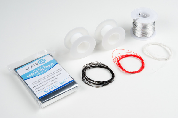
The SparkFun spools of Hookup wire, when emptied, make excellent light weight housing for the tiny servos. The lips of the servos just barely catch the edges of the center of the spool, and that's where I hot glued it in place. There are also holes in the spools, a perfect location to feed the wires from the servo motors through. Wrap this up in some of the maylar emergency blanket, and use as little tape as you can to secure it. You can repeat the same process using little paper or plastic cups. To attach the wings to the servos, I used the horns that came with the servos and hot glued the excess wire to the servo attachments. When you start testing, keep a marker handy so you can mark which one is left and which one is right.
Attach Wings
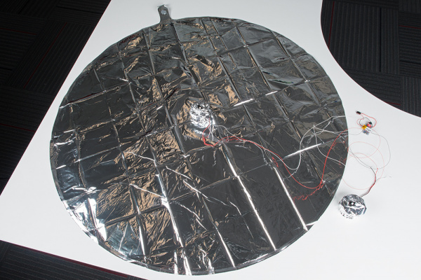
With the balloon deflated and flat on a surface, locate the center-middle and secure the servo enclosure there with a little clear packing tape. Make sure it is flat and taught, you don't want to rip the balloon when you inflate it. Here is where you want to make sure you cut yourself enough wire. I budgeted 18" of wire, which ended up too long. The electronics shouldn't hang more than 2" at the bottom when both wings are attached. I think 12" of wire should do the trick.
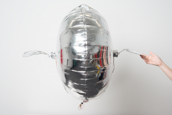
Tape down the other wing on the other side in same place. Do a test run (have someone help - it's a two person job) to make sure the left and right fins are working properly.
Inflate!
Once you have the wings secured, fill the balloon with helium, and slide the switch to power the Pro Mini from the battery.
Play!
I used the same method as in the Hook-Up Guide and the Windbag Alert for finding "volts". I used the code from the SparkFun Inventor's Kit: Experiment 8: Driving a Servo Motor and modified it for this project. Pritika's servo code for the motor functions is incredible and has a bit more finesse. Her code also uses a different Library for the Servo motor functions. If you user her code you will need to make just a couple modifications. First, download and open the SoftwareServo.h Libary file. Replace "#include <WProgram.h>" with "#include <Arduino.h>", and then make sure the library is in your Arduino file path. If you would like to see more of Pritika's work, you can find the original Ollie and Other Works. Ollie is registered under the Creative Commons Attribution-ShareAlike 3.0 Unported License so share your projects under the same.
Resources and Going Further
A quick Google search for "Electret Mic Breakout" will get you going for any type of project you may want to create. Here are a few of my favorites from Instructables.
If you need to add sound to your next project but need something a little more sensitive, robust or a little more useful, I recommend the SparkFun Sound Detector.
Documents
For more audio fun, check out these other great SparkFun tutorials:
My Drunk Kitchen Apron
SparkPunk Hookup Guide
SparkFun Inventor's Kit for Photon Experiment Guide
Spectacle Audio Board Hookup Guide
Or check out this blog post for inspiration:
