DIY Light Sculpture
 Feldi
Feldi 
Introduction
Design and build time: 5 Hours
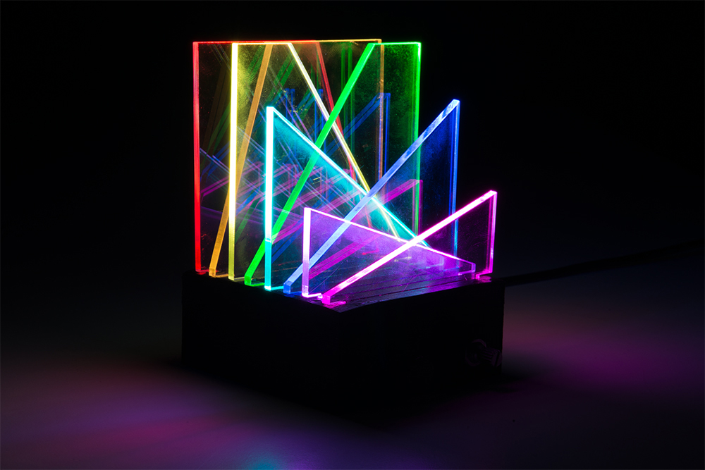
In this project, we’ll create a beautiful desktop light sculpture by edge-lighting laser cut acrylic with addressable LEDs. This project is embedded with a QDuino Mini, 8x8 Adafruit Neopixel Matrix, potentiometer, momentary pushbutton, and switch.
Required Materials
Let's go over all of the things you'll need to put your project together. Depending on what you have, you may not need everything listed here. Add it to your cart, read through the guide, and adjust the cart as necessary.
Tools
You will need a soldering iron, solder, and general soldering accessories as well as a 3D printer and black filament:
ABS Filament 3mm - 1kg (Black)
TOL-12954
TAZ 6 3D Printer
TOL-13880You will also need the following items:
- Laser Cutter
- Clear Acrylic (1/8" thick)
- Hot Glue Gun and Glue
Suggested Reading
Before you get started, take some time to familiarize yourself with the following:
How to Solder: Through-Hole Soldering
Installing an Arduino Library
Working with Wire
What is an Arduino?
Installing Arduino IDE
Addressable LED Strip Hookup Guide
Software Installation
Arduino IDE
The Qduino Mini is programmable via the Arduino IDE. If this is your first time using Arduino, please review our tutorial on installing the Arduino IDE.
Installing Arduino IDE
Qduino Mini Drivers and Board Add-On
If this is your first time working with the Qduino Mini, you may need to add drivers and the board add-on through the boards manager. Please visit the Qduino Mini quick start guide for detailed instructions on installing drivers and programming a Qduino Mini via the Arduino IDE.
Example Code
Note: This example assumes you are using the latest version of the Arduino IDE on your desktop. If this is your first time using Arduino, please review our tutorial on installing the Arduino IDE. If you have not previously installed an Arduino library, please check out our installation guide.
In this program, we will also be utilizing the Adafruit Neopixel Library. You can obtain this library through the Arduino Library Manager. Search for Adafruit Neopixel and you should be able to install the latest version of the library. If you prefer downloading the library manually you can grab it from the GitHub repository:
We have provided the code for this project below. Copy and paste it into your Arduino IDE and then upload it to your board. Make sure you have the correct board selected in the boards manager as well as the port under the port drop down.
language:c
    /******************************************************************************
  lightsculpture.ino
  Melissa Felderman @ SparkFun Electronics
  creation date: July 31, 2018


  Resources:
  Adafruit_NeoPixel.h - Adafruit Neopixel library and example functions

*****************************************************************************/

        #include <Adafruit_NeoPixel.h> //include afafruit library
    #define PIN 6 //LED matrix pin
    #define brightPot A0 //potentiometer to controll brightness
    #define pwrSwitch 4 //power switch
    #define momBut 5 //button to control LED mode
    int numPix = 64; //total LED count
    int brightPotVal; //Variable to hold pot value
    int pixelBrightness; //variabe to hold brightness value
    int switchState; //variable to hold switch value
    int butState; //variable to hold button value
    int mode = 0; //starting mode for switch state
    int prevButState = LOW;
    boolean butBool = false;
    int topMode = 4; //max number of LED modes in switch state

    unsigned long lastDebounceTime = 0;
    unsigned long debounceDelay = 200;

    Adafruit_NeoPixel strip = Adafruit_NeoPixel(numPix, PIN, NEO_GRB + NEO_KHZ800); //declare neopixel matrix


    //create an array for each row of LEDs
    int rowOne[] = {0, 1, 2, 3, 4, 5, 6, 7};
    int rowTwo[] = {8, 9, 10, 11, 12, 13, 14, 15};
    int rowThree[] = {16, 17, 18, 19, 20, 21, 22, 23};
    int rowFour[] = {24, 25, 26, 27, 28, 29, 30, 31};
    int rowFive[] = {32, 33, 34, 35, 36, 37, 38, 39};
    int rowSix[] = {40, 41, 42, 43, 44, 45, 46, 47};
    int rowSeven[] = {48, 49, 50, 51, 52, 53, 54, 55};
    int rowEight[] = {56, 57, 58, 59, 60, 61, 62, 63};

    void setup() {
      Serial.begin(9600);
      strip.begin();
      strip.show();

      pinMode(momBut, INPUT);
      pinMode(pwrSwitch, INPUT);

    }


    void loop() {
      brightPotVal = analogRead(brightPot);
      pixelBrightness = map(brightPotVal, 0, 1023, 0, 200);

      switchState = digitalRead(pwrSwitch);
      butState = digitalRead(momBut);

      strip.setBrightness(pixelBrightness);
      strip.show();

      //function to debounce button
      if ((millis() - lastDebounceTime) > debounceDelay) {
        if ((butState == HIGH) && (butBool == false)) {
          butBool = true;
          mode++;
          lastDebounceTime = millis();
        } butBool = false;
      } if (mode > topMode) {
        mode = 0;
      }

      Serial.println(mode);

      //switch state function to cycle through modes on LEDs, you can add as many or as few as you would like
      if (switchState == HIGH) {

        switch ( mode ) {
          case 0:
            for (int i = 0; i < numPix; i++) {
              strip.setPixelColor(i, 255, 255, 255);
            }
            strip.show();
            break;
          case 1:
            rainbow();
            break;
          case 2:
            buleGreenGradient();
            break;
          case 3:
            pinkGradient();
            break;
          case 4:
            yellowGradient();
            break;

        }
      } else if (switchState == LOW) {
        for (int i = 0; i < numPix; i++) {
          strip.setPixelColor(i, 0, 0, 0);
        }
        strip.show();
      }
    }


    //functions for LED colors


    void everyOther() {
      for (int i = 0; i < 8; i++) {
        strip.setPixelColor(rowOne[i], 255, 255, 255);
        strip.setPixelColor(rowThree[i], 255, 255, 255);
        strip.setPixelColor(rowFive[i], 255, 255, 255);
        strip.setPixelColor(rowSeven[i], 255, 255, 255);

        strip.setPixelColor(rowTwo[i], 0, 0, 0);
        strip.setPixelColor(rowFour[i], 0, 0, 0);
        strip.setPixelColor(rowSix[i], 0, 0, 0);
        strip.setPixelColor(rowEight[i], 0, 0, 0);
      }
      strip.show();
    }


    void pinkGradient() {
      for (int i = 0; i < 8; i++) {
        strip.setPixelColor(rowOne[i], 185, 0, 255);
        strip.setPixelColor(rowTwo[i], 195, 0, 230);
        strip.setPixelColor(rowThree[i], 205, 0, 200);
        strip.setPixelColor(rowFour[i], 215, 0, 160);
        strip.setPixelColor(rowFive[i], 225, 0, 120);
        strip.setPixelColor(rowSix[i], 235, 0, 80);
        strip.setPixelColor(rowSeven[i], 245, 0, 40);
        strip.setPixelColor(rowEight[i], 255, 0, 10);
      }
      strip.show();
    }

    void buleGreenGradient() {
      for (int i = 0; i < 8; i++) {
        strip.setPixelColor(rowOne[i], 0, 75, 255);
        strip.setPixelColor(rowTwo[i], 0, 100, 225);
        strip.setPixelColor(rowThree[i], 0, 125, 200);
        strip.setPixelColor(rowFour[i], 00, 150, 175);
        strip.setPixelColor(rowFive[i], 0, 175, 150);
        strip.setPixelColor(rowSix[i], 0, 200, 125);
        strip.setPixelColor(rowSeven[i], 0, 225, 100);
        strip.setPixelColor(rowEight[i], 0, 255, 75);
      }
      strip.show();
    }

    void yellowGradient() {
      for (int i = 0; i < 8; i++) {
        strip.setPixelColor(rowOne[i], 255, 255, 25);
        strip.setPixelColor(rowTwo[i], 255, 220, 25);
        strip.setPixelColor(rowThree[i], 255, 190, 25);
        strip.setPixelColor(rowFour[i], 255, 160, 25);
        strip.setPixelColor(rowFive[i], 255, 130, 25);
        strip.setPixelColor(rowSix[i], 255, 100, 25);
        strip.setPixelColor(rowSeven[i], 255, 70, 25);
        strip.setPixelColor(rowEight[i], 255, 40, 25);
      }
      strip.show();
    }
    void rainbow() {
      for (int i = 0; i < 8; i++) {
        strip.setPixelColor(rowOne[i], 255, 0, 0);
      } for (int i = 0; i < 8; i++) {
        strip.setPixelColor(rowTwo[i], 255, 100, 0);
      } for (int i = 0; i < 8; i++) {
        strip.setPixelColor(rowThree[i], 255, 255, 0);
      } for (int i = 0; i < 8; i++) {
        strip.setPixelColor(rowFour[i], 0, 255, 0);
      } for (int i = 0; i < 8; i++) {
        strip.setPixelColor(rowFive[i], 0, 255, 200);
      } for (int i = 0; i < 8; i++) {
        strip.setPixelColor(rowSix[i], 0, 0, 255);
      } for (int i = 0; i < 8; i++) {
        strip.setPixelColor(rowSeven[i], 255, 0, 255);
      } for (int i = 0; i < 8; i++) {
        strip.setPixelColor(rowEight[i], 255, 0, 130);
      }
      strip.show();
    }
Understanding Your Circuit
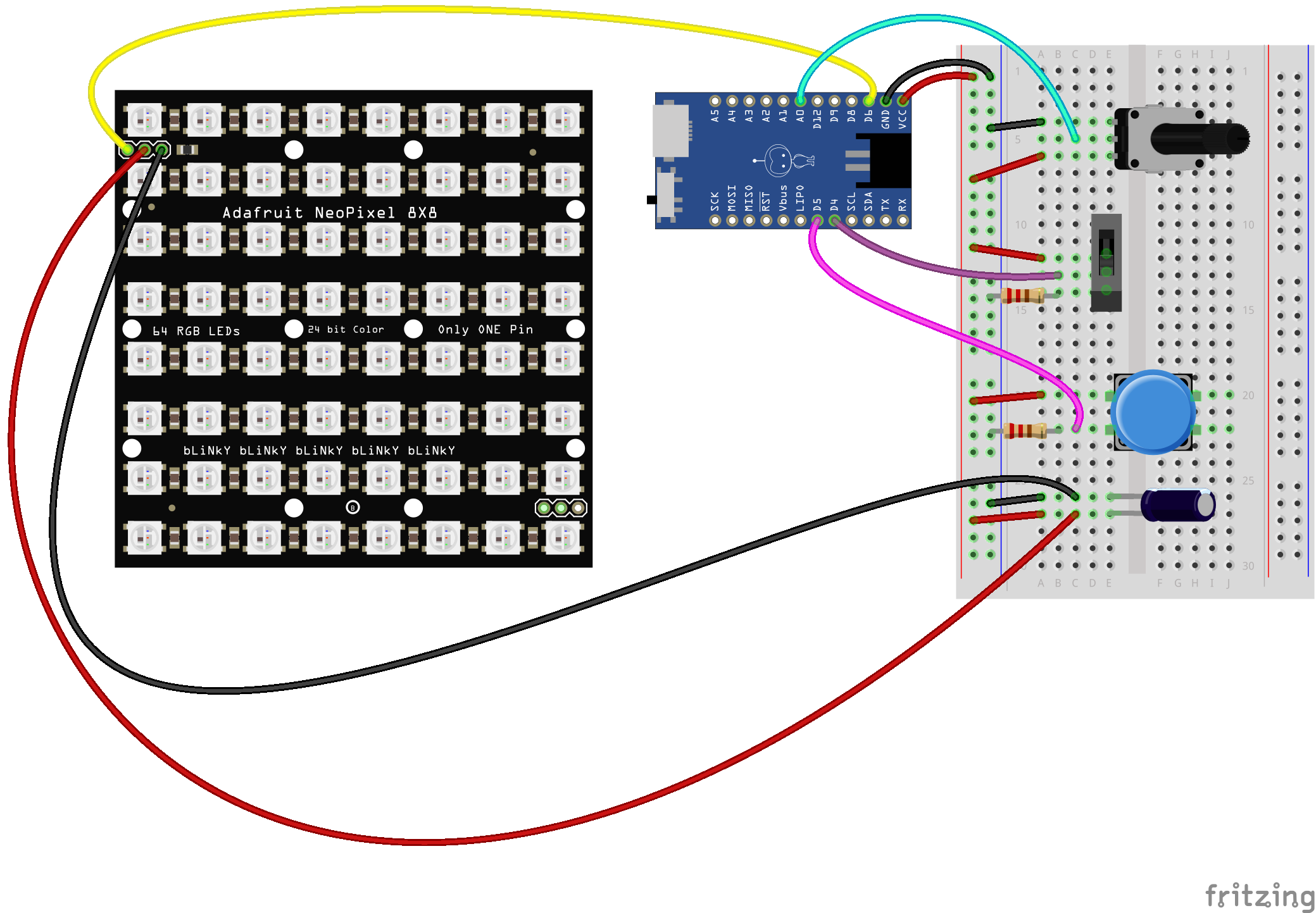
Inside the light sculpture enclosure is one NeoPixel NeoMatrix 8x8 - 64 RGB LED containing a total of 64 addressable WS2812 LEDs, a 100uF Capacitor to protect the first LED, one Qduino Mini - Arduino Dev Board to act as the brains of the project, a Mini Power Switch to easily turn the project on or off, a Tactile Button to navigate between light modes, and a Potentiometer to control brightness. A small piece of Snappable Protoboard is used to extend the '+' and '-' terminals on the Qduino Mini making it easier to connect the '+' and '-' leads from your components. A MicroB USB cable is used to supply wall power directly to the USB port on the Qduino, but a large LiPo battery would work as well.
As shown in the circuit diagram below, the Qduino Mini is the brains of this project. Pin D6 is connected to the NeoPixel NeoMatrix, the potentiometer is connect to pin A0, the switch to pin D4, and the momentary pushbutton to D5. The first LED on the NeoPixel Matrix is protected using a 100uF capacitor between '+' and '-' on the matrix and '+' and '-' on the Qduino Mini. You may also notice that while the rest of the components directly connect to '+' on the Qduini Mini, the switch and button both connect to '-' of the Qduino via a resistor. This is called a pulldown resistor and allows the Qduino to get accurate readings of HIGH and LOW. To learn more about how to use pull up and pull down resistors with Arduino, check out our tutorial.
Enclosure Fabrication
The first part of this project is printing the enclosure on a 3D printer. If you do not have access to a 3D printer, check with your local library or maker space. There are also 3D printing services which you can use online like Shapeways.
Download 3D Printer Drivers
Download any drivers and firmware needed to control your 3D printer. If you are working with a LulzBot like the ones sold through SparkFun, check out their downloads page in the support section of their website. If you are working with a different printer, check out the printer brand's website for information on drivers and firmware.
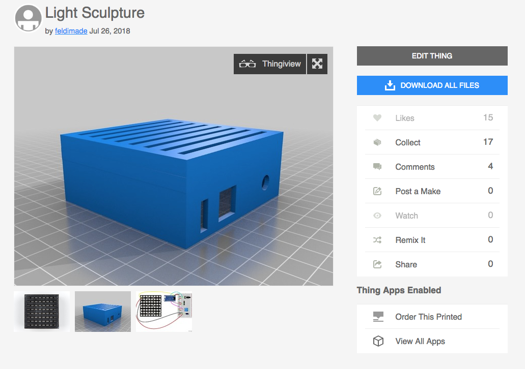
Download Project File
Download the .stl file from the project page on thingiverse.
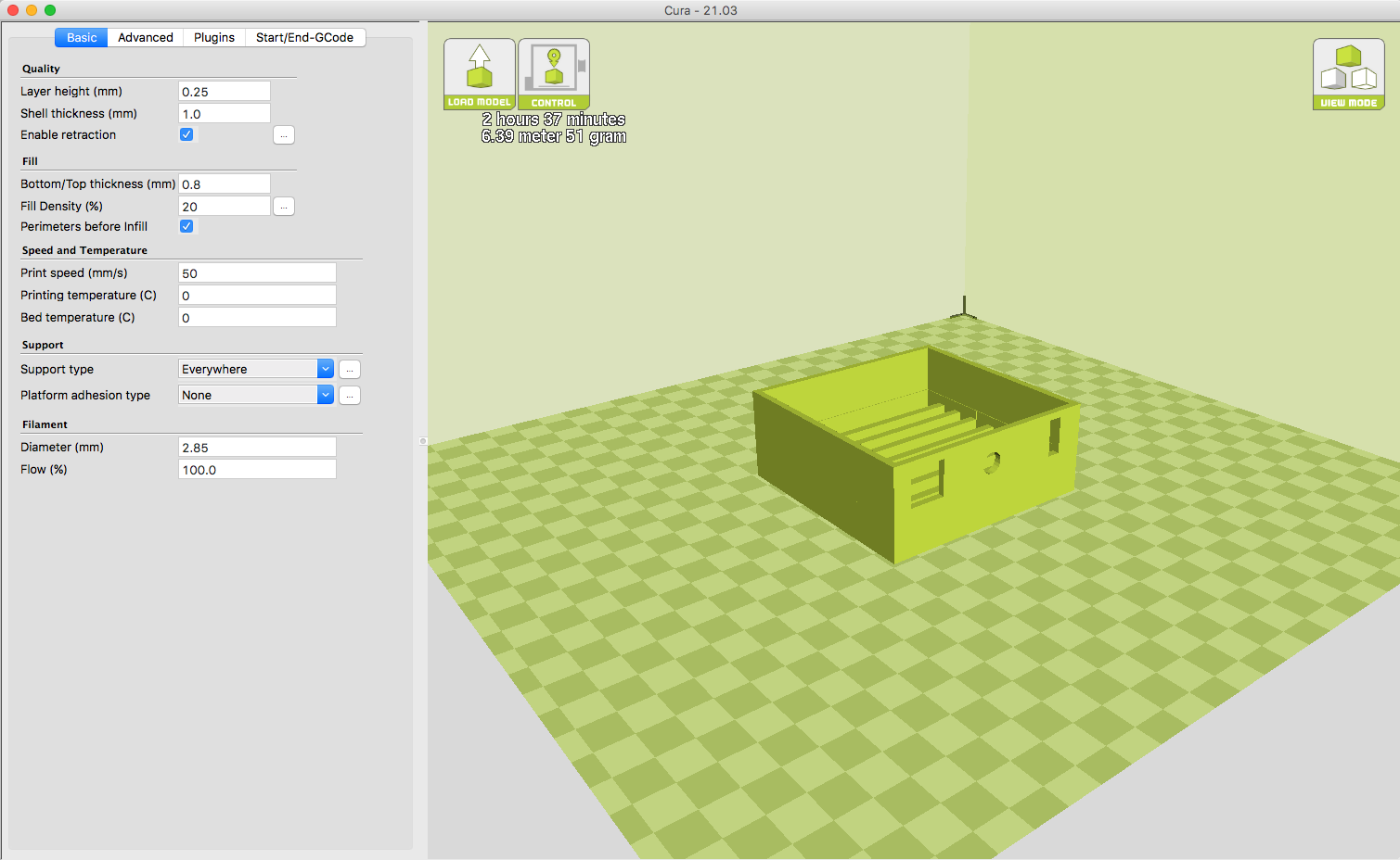
Prepare GCode
Prepare your Gcode by loading the .stl into your driver software. Either save the Gcode to an SD card or prepare to print by connecting your computer to the printer via USB. Make sure your settings match the material you plan to use. I recommend using black filament because it is effective in blocking light. A lighter color may leak light. If you prefer a light colored enclosure, I would print it in black and then spray paint it afterwards before adding the electronics.
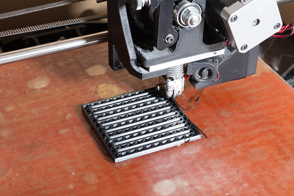
Print the enclosure!
Putting Your Electronics Together
Now that we have printed the enclosure, let's prepare the electronics for our circuit.
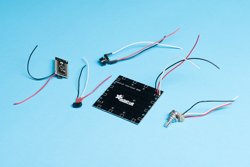
Solder Wire Leads
Solder wire leads of about 2" to your components using solid core hook up wire. To make things easier for yourself later, use red wire for '+', black from GND, and white for GPIO input/output. Use heat shrink to secure and isolate your connections on the button and switch.
Place Electronics
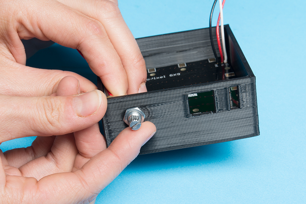
Place the electronics in their respective spaces in the enclosure. For the NeoPixel matrix, make sure your DIN pin is in the opposite corner of the potentiometer. This is to ensure your LED patterns align with the slots. You can secure the potentiometer in place with the nut that comes with it.
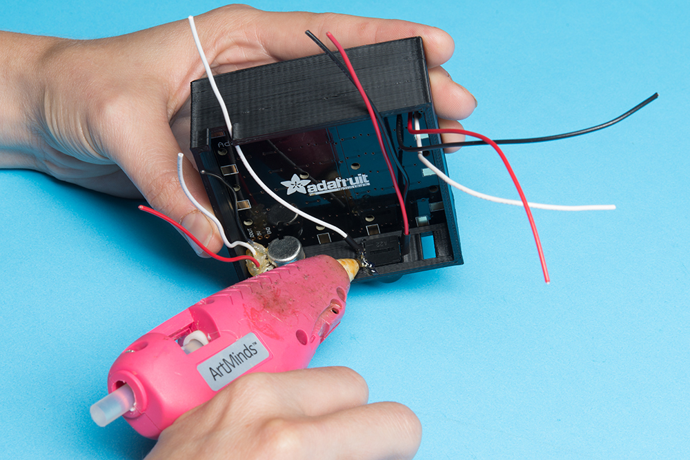
For the button and switch, use a small dab of hot glue on the backside to hold them in place.
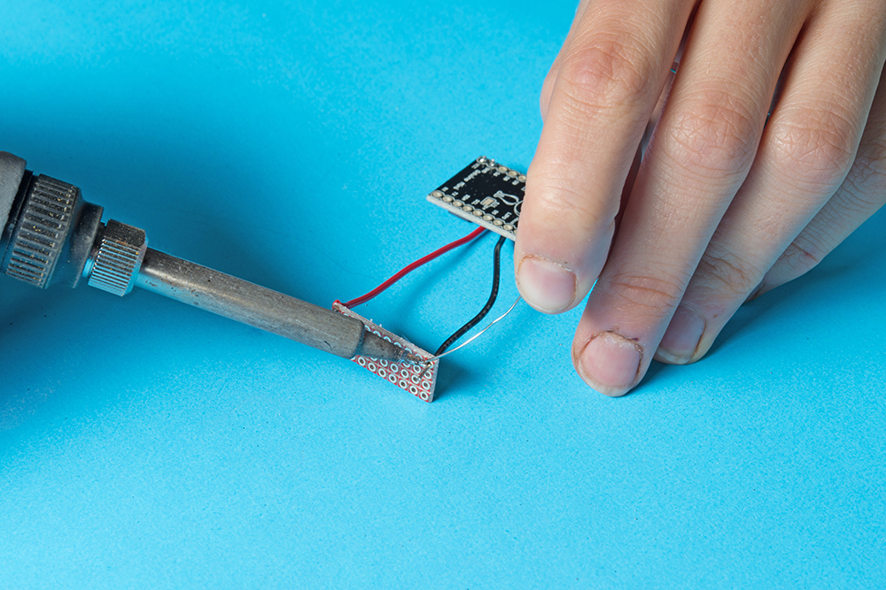
Solder a '+' and '-' lead to the VCC and GND of your Qduino respectively. There is only one '+' and one '-' pin on the Qduino so we will need to extend these two pins in order for your components to connect. To do this, grab a small piece of protoboard and solder the opposite end of the '+' lead to one corner and the opposite end of the '-' lead to the opposite corner.
Plug the USB cable into the Qduino and place it face down behind the potentiometer with the USB cable threaded through the tab in the back of the enclosure.
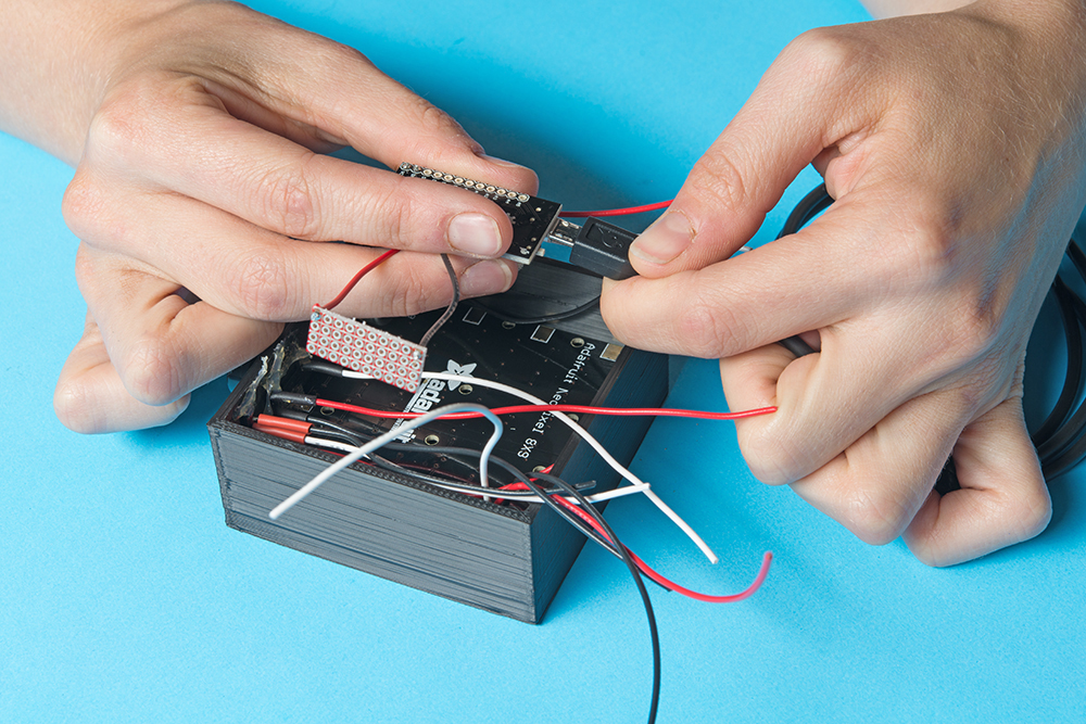
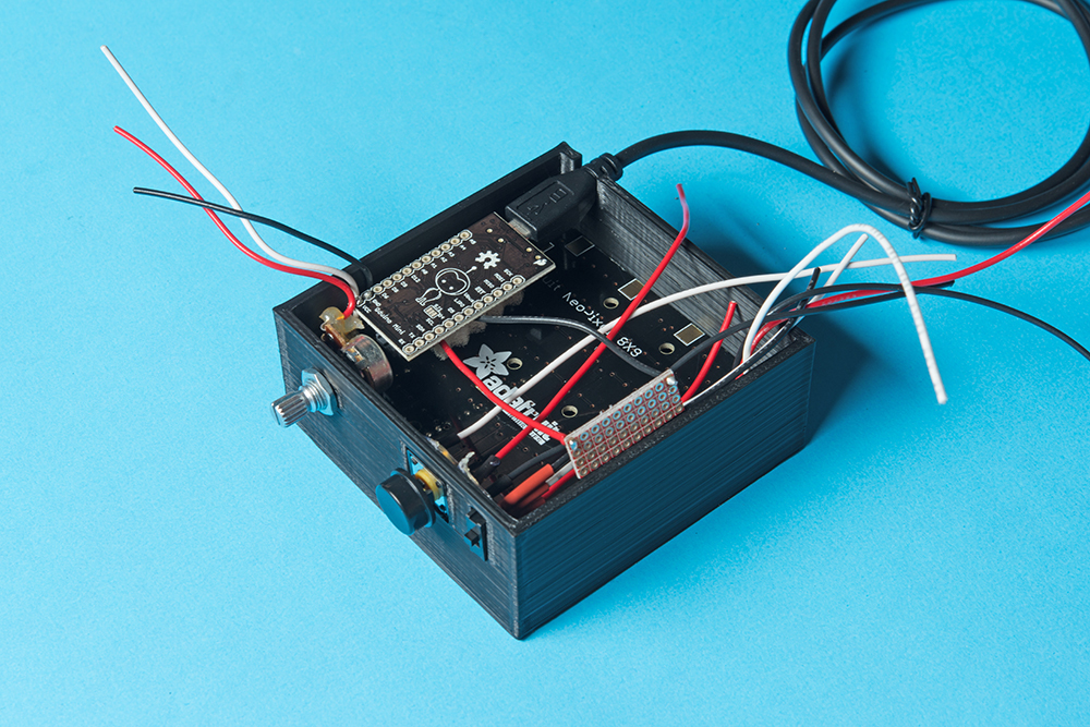
Before you begin soldering your circuit together, all parts in the enclosure should look like this:
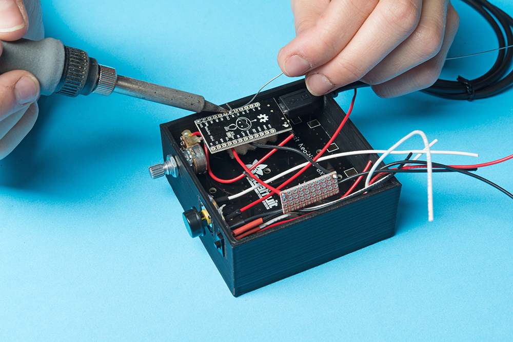
Solder Circuits
Solder your circuit together according to the fritzing diagram provided above. Use the '+' and '-' extensions on the protoboard for all of your '+' and '-' leads. Don't forget to solder a resistor between the GND extension and the the GND leads on your switch and button. It is also best practice to use a capacitor between the '+' and '-' leads on your NeoPixel matrix and the '+' and '-' extensions to protect the first LED from a rush of current.
Verify
Test your circuit. Turn it on and make sure it is working according to the program.
Laser Cutting Your Design
Now that we have the base enclosure completed with the electronics soldered together into a circuit, let's take a look at how to add a decorative flair to your project.
Download Templates
Download the laser cutter template from the project thingiverse page to prepare to cut your acrylic inserts. Open this with illustrator and begin to design your etching and/or cuts. I have found that the light is picked up by both the etched design and the edges of the plastic, so you can use both of these elements to create your final design. There are 8 rows of LEDs on your matrix so you will want to make 8 different acrylic inserts.
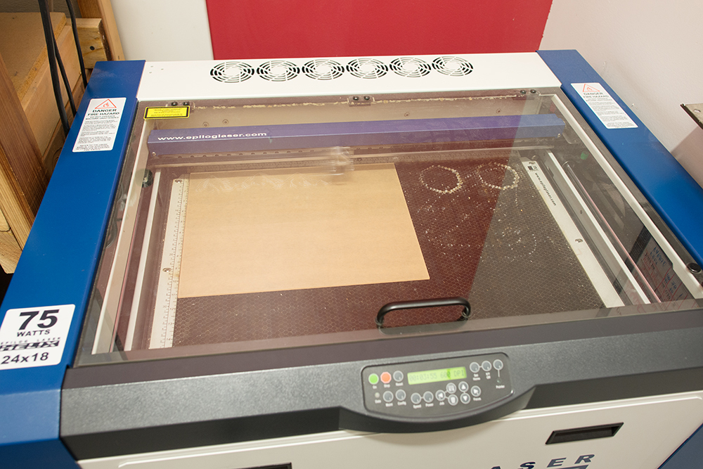
Cut Your Designs
These inserts were cut and the designs rastered on our Epilog 75W laser cutter according to the manufacturer's specifications. If you do not have access to a laser cutter, check out your local library or hackerspace. Alternatively, you can order your designs online at Ponoko.
Light up your Life!
Pop the inserts into your enclosure and enjoy!
Resources and Going Further
For more information related to this tutorial, check out the following links:
- Qduino Quick Start Guide
- Shapeways
- Ponoko
- Thingiverse Project Page
- NeoPixel GitHub Repo
- WS2812 LED Datasheet (PDF)
There is some great information on the WS2812s as well as powering LED projects in the following tutorials:
WS2812 Breakout Hookup Guide
RGB Panel Hookup Guide
Mean Well LED Switching Power Supply Hookup Guide
Looking for another project? Have a look at some of the following tutorials:
Marquee Party Bag
DIY Light-Up Shoes
DIY Heated Earmuffs
Check out these blog posts for even more great ideas!