DIY Heated Earmuffs
 Feldi
Feldi 
Introduction
Design and build time: 5 Hours
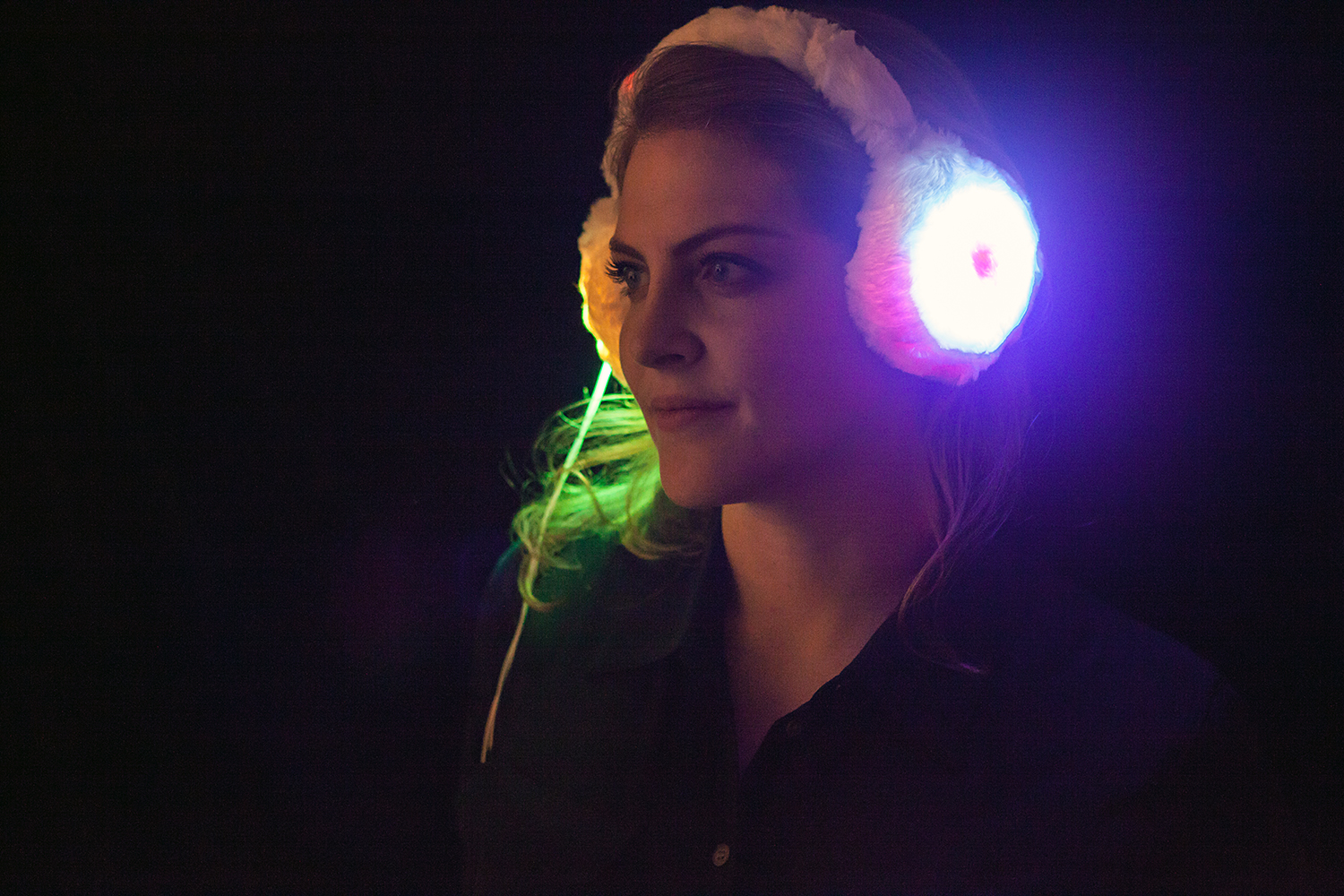
In this project, we’ll create a wearable pair of heated earmuffs with decorative addressable LEDs. These earmuffs are embedded with a Pro Micro 5v, two heating pads, and four rings of WS2812 addressable LEDs, or 'Neopixels'. This project is designed to keep the user extra warm while still looking stylish.
Suggested Reading
Before you get started, take some time to familiarize yourself with the following:
How to Solder: Through-Hole Soldering
Installing an Arduino Library
Working with Wire
What is an Arduino?
Installing Arduino IDE
Planning a Wearable Electronics Project
Addressable LED Strip Hookup Guide
Materials and Tools
Let's go over all of the things you'll need to put your project together.
You Will Also Need:
- Hook Up Wire
- Soldering Iron
- Solder
- Flush Cutters
- Wire Strippers
- Heat Shrink
- Heat Gun
- Foam (1" thick)
- Interfacing
- Matte Board or Cardboard
- Headband
- Hot Glue Gun and Glue
- Soft Fabric
- Scissors
- Soft Silicone Wire
- Disappearing Ink Marker
- Ruler
Software Installation
Arduino IDE
The Pro Micro 5V is programmable via the Arduino IDE. If this is your first time using Arduino, please review our tutorial on installing the Arduino IDE.
Installing Arduino IDE
Pro Micro Drivers and Board Add-On
If this is your first time working with the Pro Micro, you may need to add drivers and the board add-on through the boards manager. Please visit the Pro Micro hookup guide for detailed instructions on installing drivers and programming a Pro Micro via the Arduino IDE.
Example Code
Note: This example assumes you are using the latest version of the Arduino IDE on your desktop. If this is your first time using Arduino, please review our tutorial on installing the Arduino IDE. If you have not previously installed an Arduino library, please check out our installation guide.
In this program, we will also be utilizing the Adafruit Neopixel Library. You can download the library below.
We have provided the code for this project below. Copy and paste it into your Arduino IDE and then upload it to your board. Make sure you have the correct board selected in the boards manager as well as the port under the port drop down.
language:c
    /******************************************************************************
  earmuffs.ino
  Melissa Felderman @ SparkFun Electronics
  creation date: January 22, 2018


  Resources:
  Adafruit_NeoPixel.h - Adafruit Neopixel library and example functions

*****************************************************************************/

#include <Adafruit_NeoPixel.h>

int heatPin = 3;
int ring = 4;


Adafruit_NeoPixel strip = Adafruit_NeoPixel(80, ring, NEO_GRB + NEO_KHZ800);

void setup() {
  pinMode(heatPin, OUTPUT);
  digitalWrite(heatPin, HIGH);
  strip.begin();
  strip.setBrightness(45);
  strip.show();

}

void loop() {
  // put your main code here, to run repeatedly:
  rainbowCycle(20);

}


// Slightly different, this makes the rainbow equally distributed throughout
void rainbowCycle(uint8_t wait) {
  uint16_t i, j;
strip.setBrightness(45);
  for (j = 0; j < 256 * 5; j++) { // 5 cycles of all colors on wheel
    for (i = 0; i < strip.numPixels(); i++) {
      strip.setPixelColor(i, Wheel(((i * 256 / strip.numPixels()) + j) & 255));
    }
    strip.show();
    delay(wait);
  }
}

// Input a value 0 to 255 to get a color value.
// The colours are a transition r - g - b - back to r.
uint32_t Wheel(byte WheelPos) {
  WheelPos = 255 - WheelPos;
  if (WheelPos < 85) {
    return strip.Color(255 - WheelPos * 3, 0, WheelPos * 3);
  }
  if (WheelPos < 170) {
    WheelPos -= 85;
    return strip.Color(0, WheelPos * 3, 255 - WheelPos * 3);
  }
  WheelPos -= 170;
  return strip.Color(WheelPos * 3, 255 - WheelPos * 3, 0);
}
Understanding Your Circuit
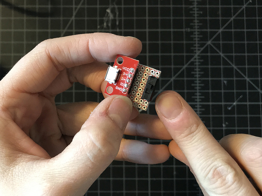
Inside the earmuffs are four NeoPixel Rings containing a total of 80 WS2812 addressable LEDs, two 5x10cm Heating Pads, a Pro Micro 5v/18MHz, a N-Channel MOSFET, one 10k resistor, two small pieces of Snappable Protoboard, and lots Hook Up Wire. The project is powered by our Lithium Ion Battery Pack via the SparkFun microB USB Breakout. A Mini Power Switch is connected to the power source for easy user control.
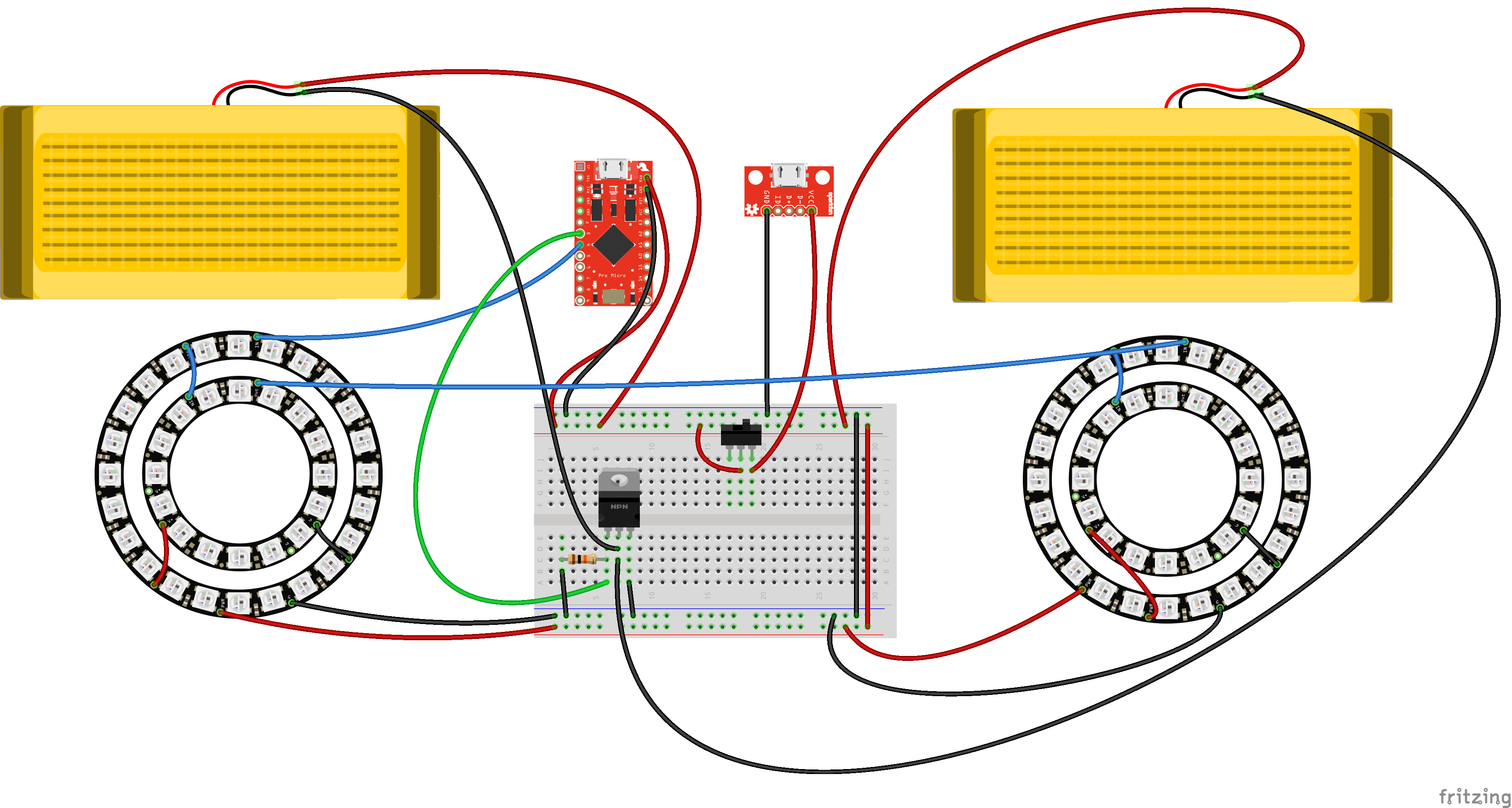
As expressed in the circuit diagram below, the Pro Micro 5v is the brains of this project. Pin 4 is connected to one of the 24x Neopixel Rings Din, with VCC connected to Raw on the Pro Micro, and GND to GND. Dout of that same Neopixel ring is connected to Din on of the 12x Neopixel Ring, VCC to VCC and GND to GND. Dout of the smaller Neopixel Ring is connected to Din on the second 24x Neopixel Ring, who's VCC and GND are connected to Raw and GND on the Microcontroller. Dout of this ring is connected to Din of the second 12x Neopixel ring, with VCC to VCC and GND to GND.
The heating pads require about ~750mA, which is more than the microcontroller I/O pin can handle. In order to accomplish that, we will be using a N-Channel Mosfet Transisitor. One lead of each of the heating pads should connect directly to RAW on the microcontroller. The second connects to the Drain (D) lead on the transistor, or the center lead. Pin 3 on the microcontroller connects to the Gain (G) lead, which is the left lead. There is also a 10k resistor pulling the G lead down to GND. Finally, the Source (S) lead connects directly to GND.
Two long flexible wires are included in the circuit. One connects to GND and one directly to Raw. The GND wire will connect to GND on the USB Breakout. The Raw wire will connect to the center lead of the switch. Finally VCC on the USB breakout will connect with a second lead on the switch.
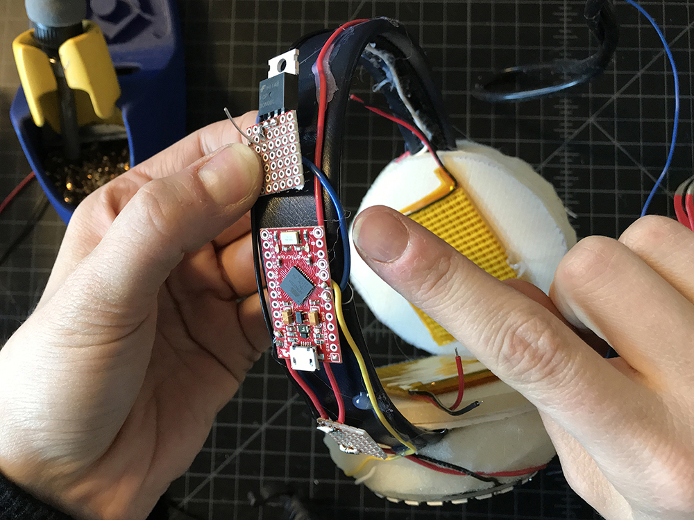
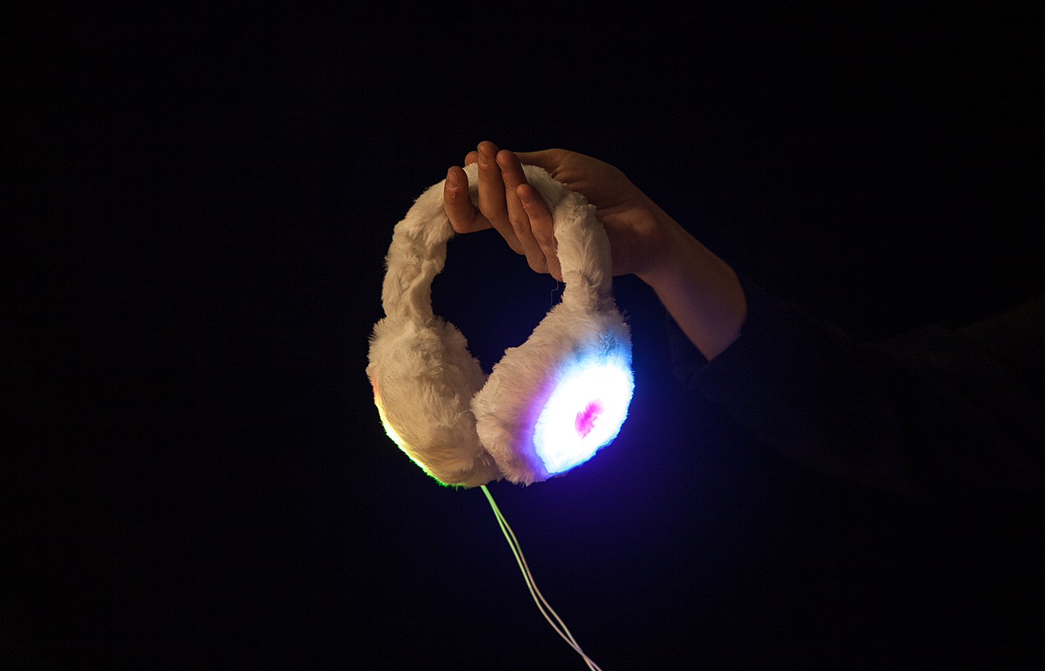
The Heated Earmuffs pose a unique design challenge as a wearable circuit in that the components require a 5v power supply. That's not something you want to wear on your head. Because of this, the Heated Earmuffs have a similar physical design to headphones, with soft flexible wires connecting the circuit above with a control switch and power source in your pocket. Not only does this put the bulky power supply in a hidden location, but it also allows the user to conveniently and discretely switch the circuit on and off.
Building the Structure
The first part of this project is building the earmuffs structure which we will build our circuit around.
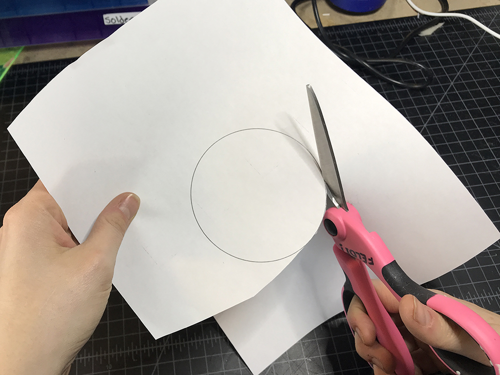
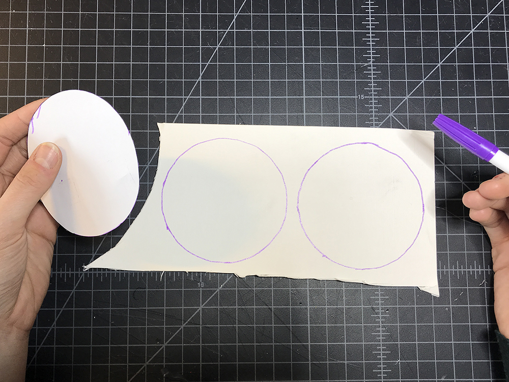
STEP 1:
Download and print out the circles template.
Then cut along the outline of each circle. Set aside the larger circle for later.
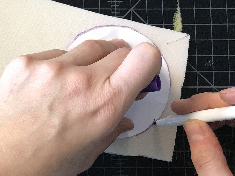
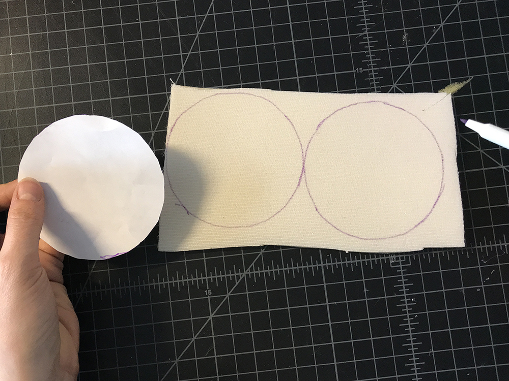
STEP 2:
Place the smaller circle on your matte board or cardboard and trace it.
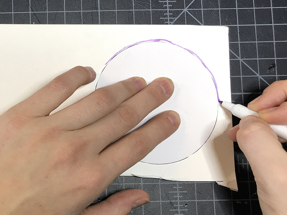
Repeat once more so that you have drawn two even circles on the matte board or card board.
STEP 3:
Cut out both circles.

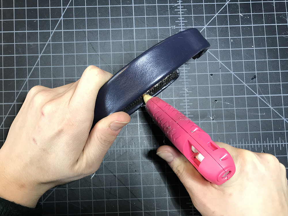
STEP 4:
Add some hot glue to the lower inch and a half of one side of the headband.
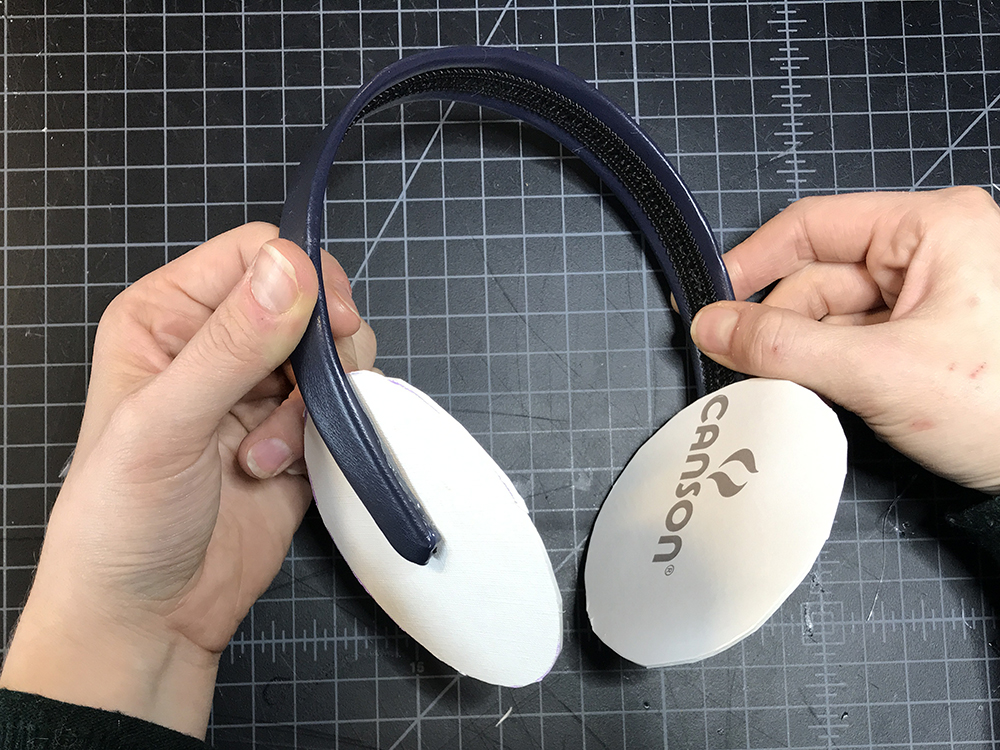
STEP 5:
Place one of the matte board of cardboard circles to the area with hot glue. The bottom point of the headband should be at the approximate center of the circle.
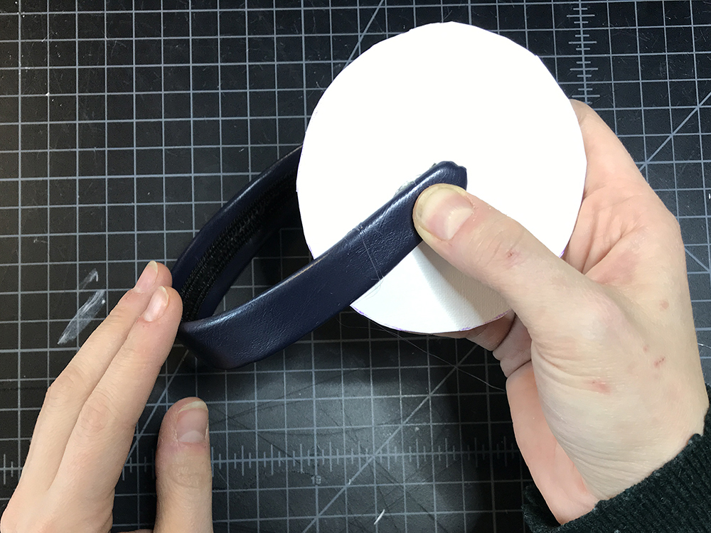
Repeat on the second side.
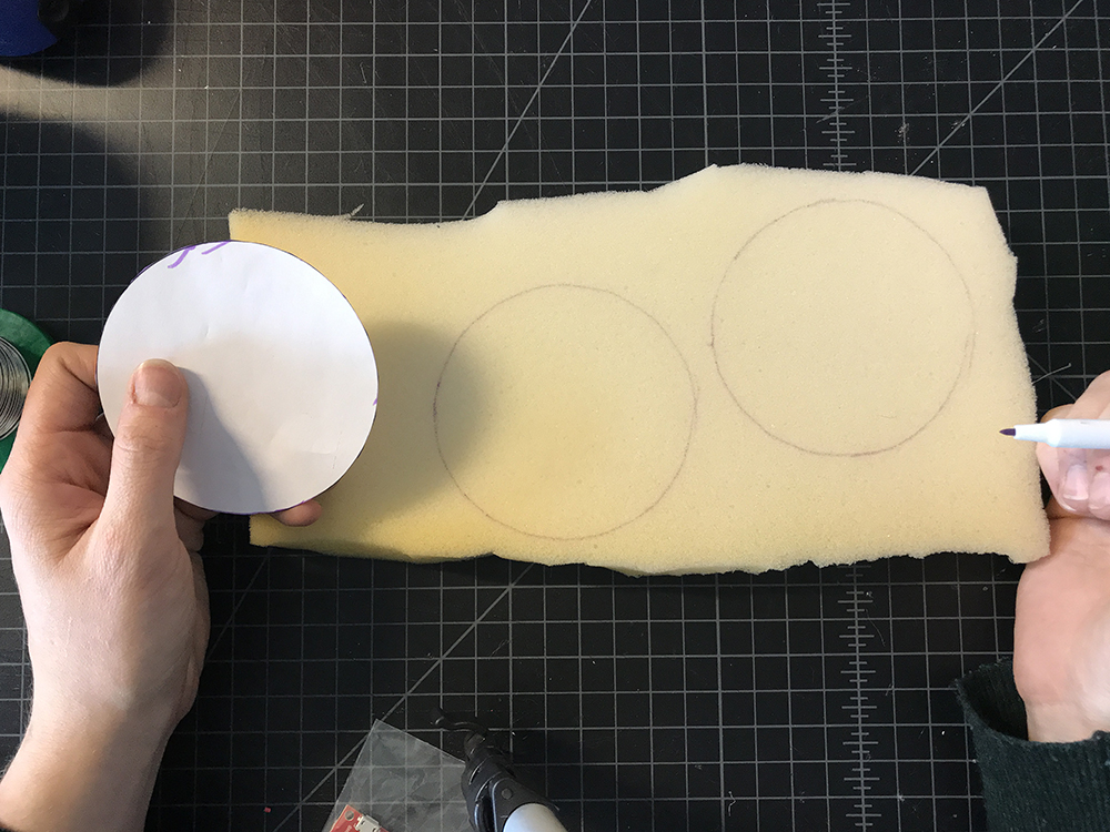
STEP 6:
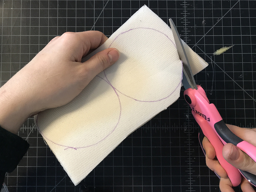
Grab the small circle template again and trace it on your foam.
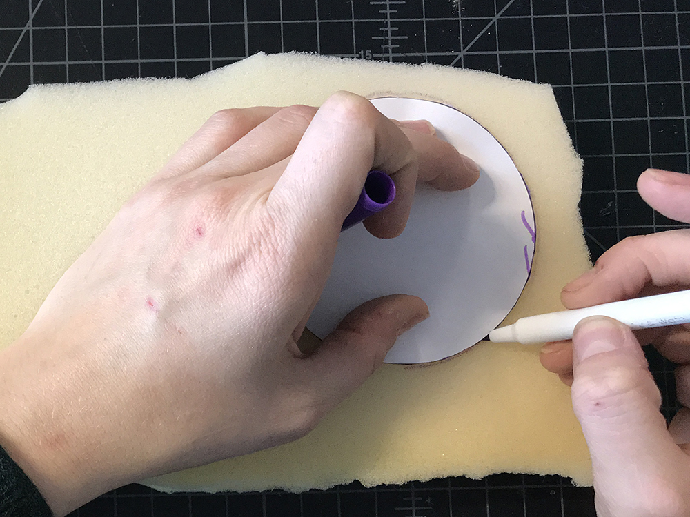
Repeat once more so you have two circles.
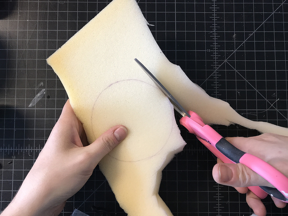
STEP 7:
Cut out both circles from the foam.
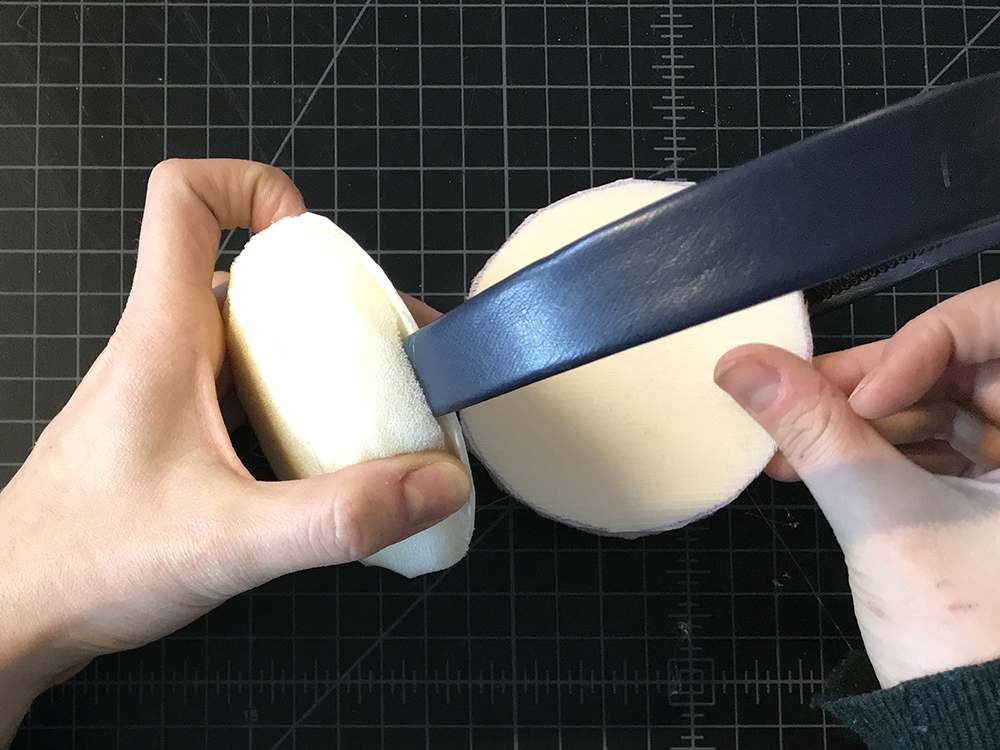
STEP 8:
Use your scissors to sculpt one side of each foam circle into a dome.
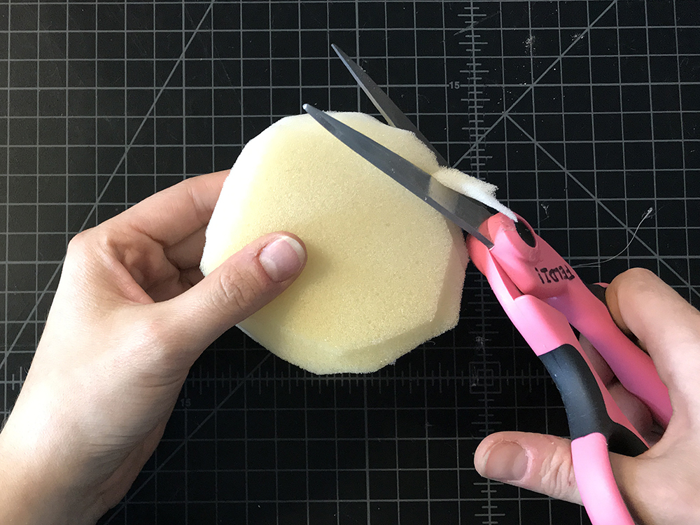
When you are done, your foam circles side view should look like this:

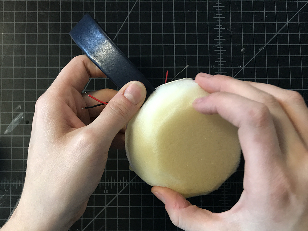
STEP 9:
Add hot glue around the perimeter of one of the circles on the headband and then place the foam dome on top. Repeat on the second side.
STEP 10:
Grab the small circle template again and trace it on to interfacing twice.
STEP 11:
Cut out both circle from the interfacing.
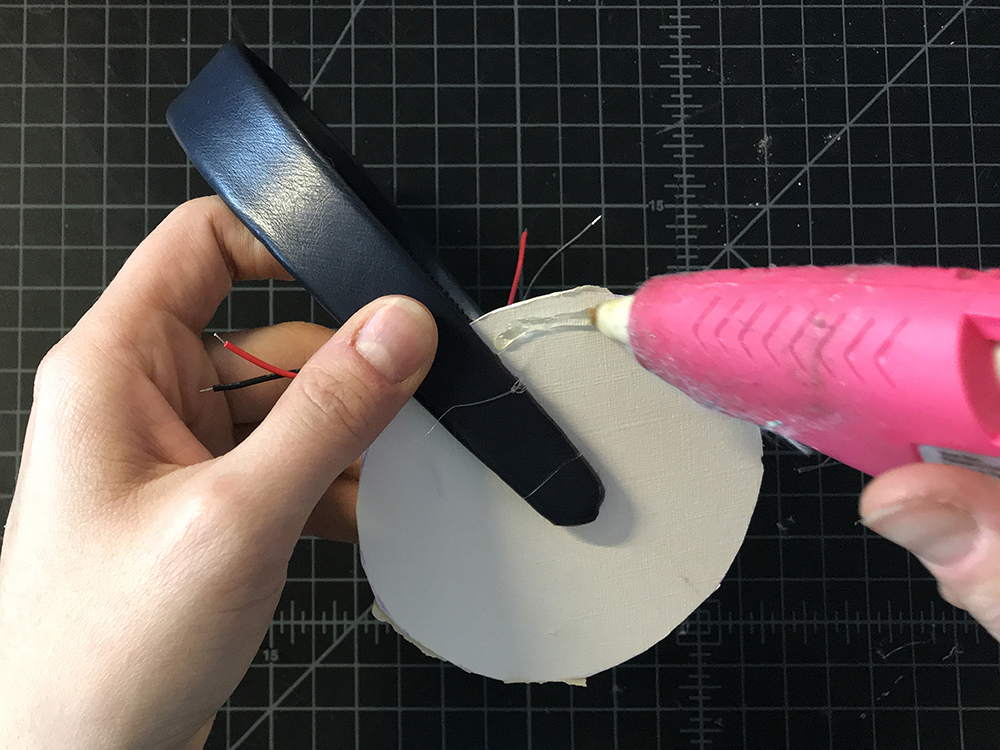
STEP 12:
Add hot glue to the perimeter of the inner side of your board circle, and then place the interfacing on top. Repeat this on the second side.

Preparing Your Electronics
Now that we have build the structure of the earmuffs, let's begin to prepare the electronics for our circuit.
STEP 13:
Add a small touch of hot glue to one edge of your heating pad, then fold it over making it half it's original size.
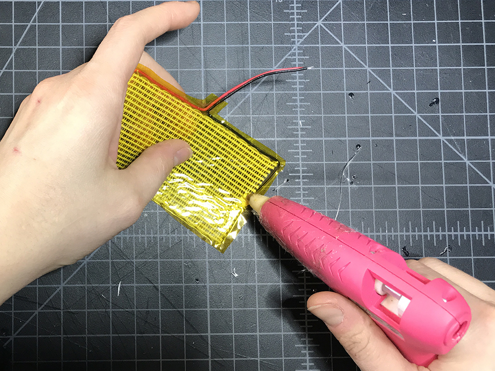

STEP 14:
On one side of the folded pad, add hot glue to all four corners.
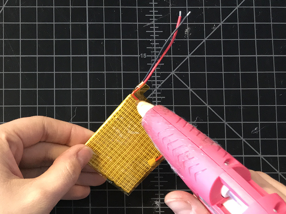
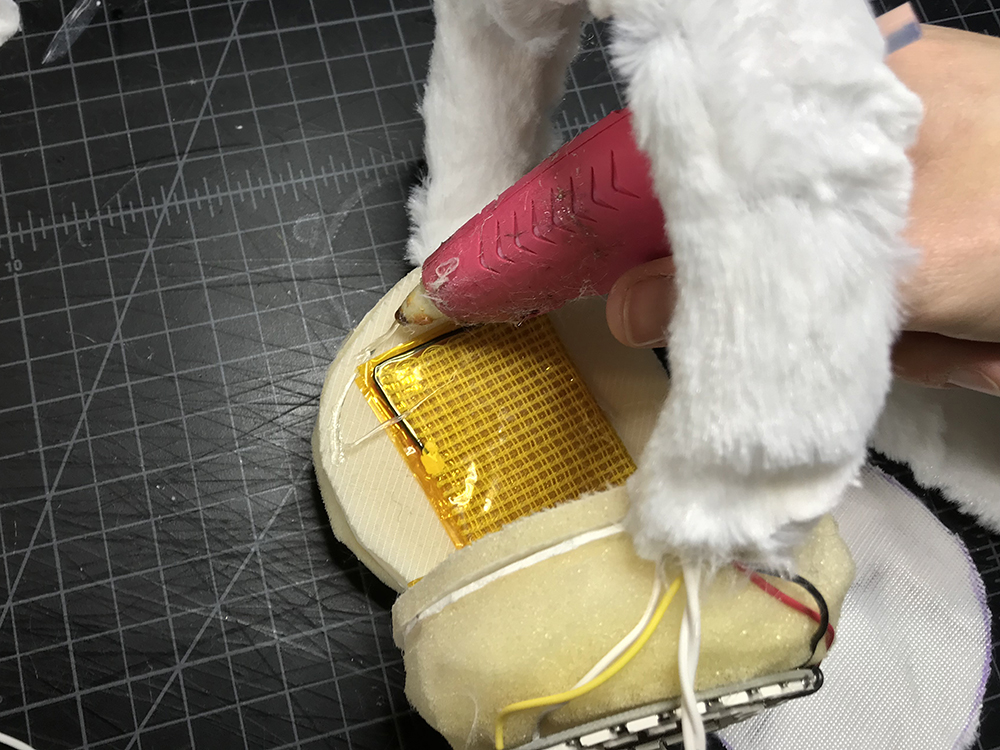
STEP 15:
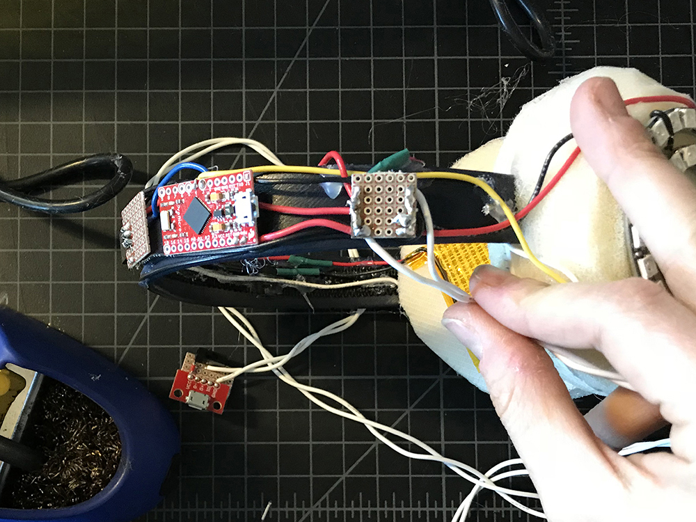
Glue it on to the interfacing, with the two leads pointing up and aligned with the leg of the headband as much as possible. Repeat for the second heating pad on the opposite side.
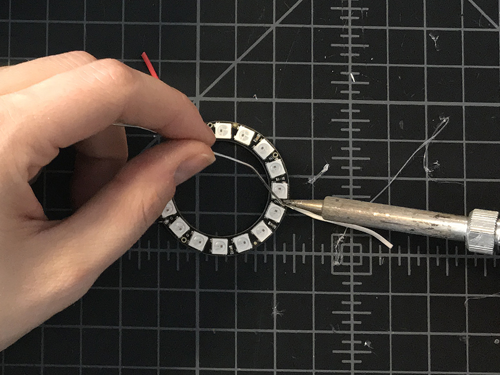
STEP 16:
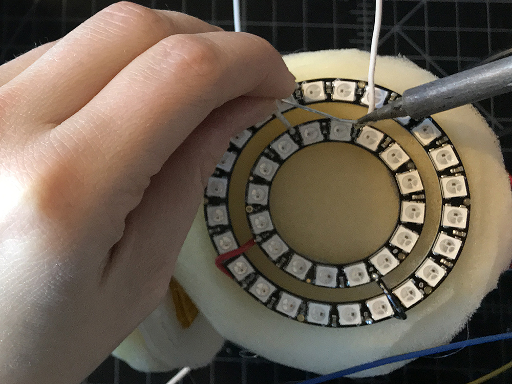
Strip a short amount of wire (about 1" - 2") and solder to both of the smaller Neopixel rings on VCC, GND, and DIN.
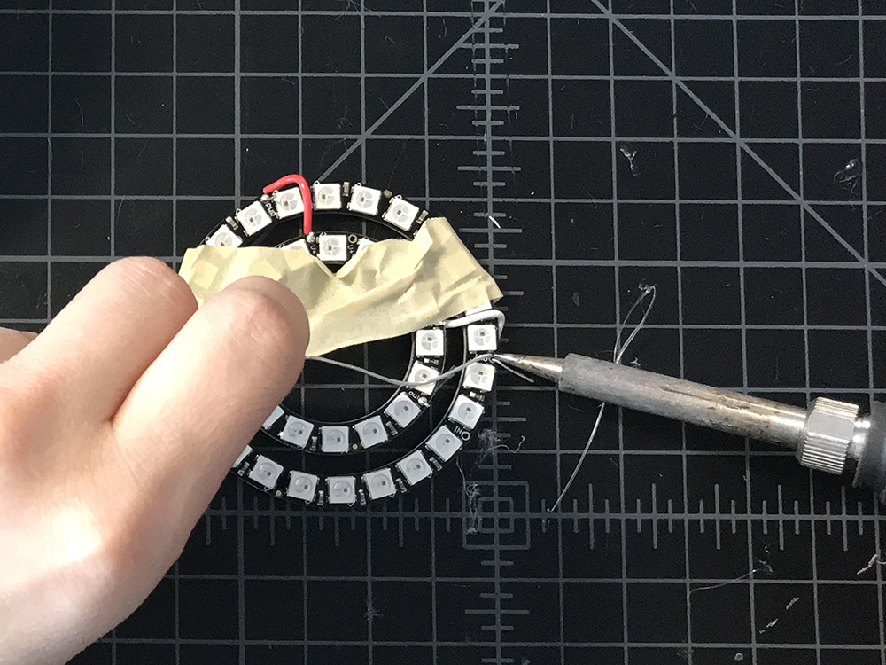
STEP 17:
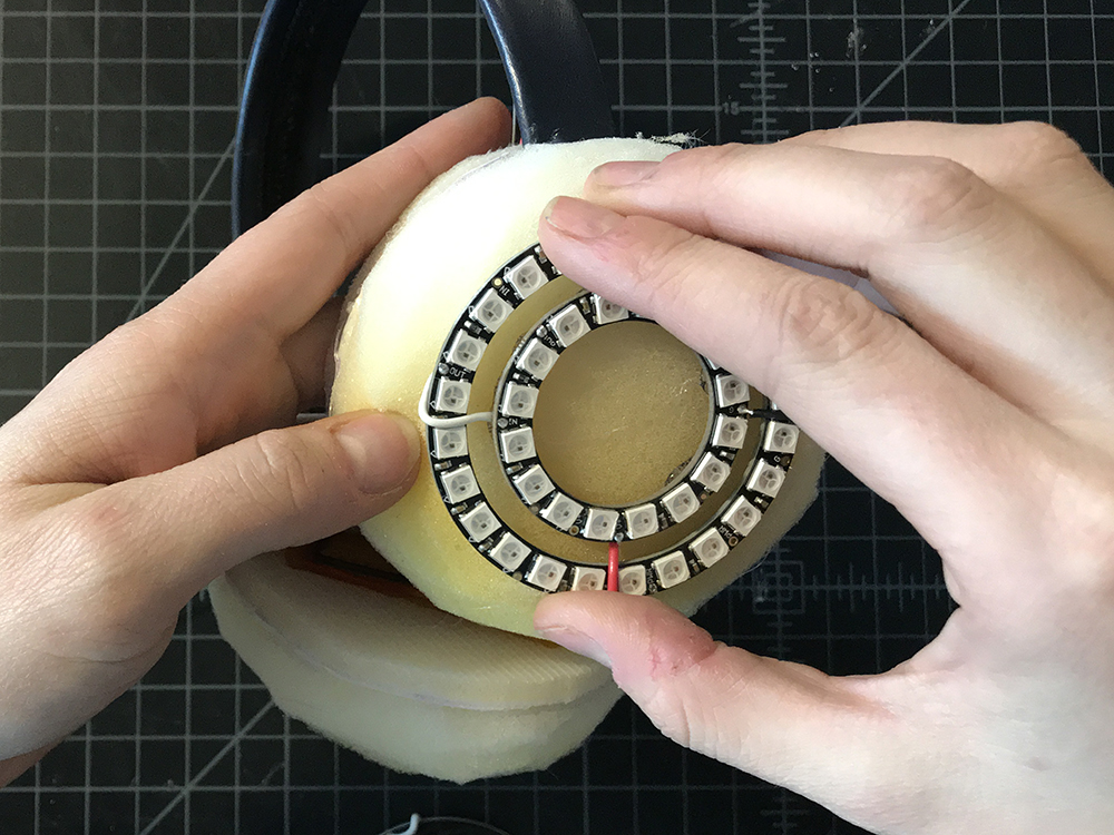
Place the larger neopixel ring around each smaller one, make sure the smaller one is relatively centered, and then add a small piece of tape over them to keep them in position.

STEP 18:
Solder the Neopixel Ring pairs together according to the circuit diagram. (From inside ring to outside ring, DIN -> DOUT, VCC -> VCC, and GND -> GND.
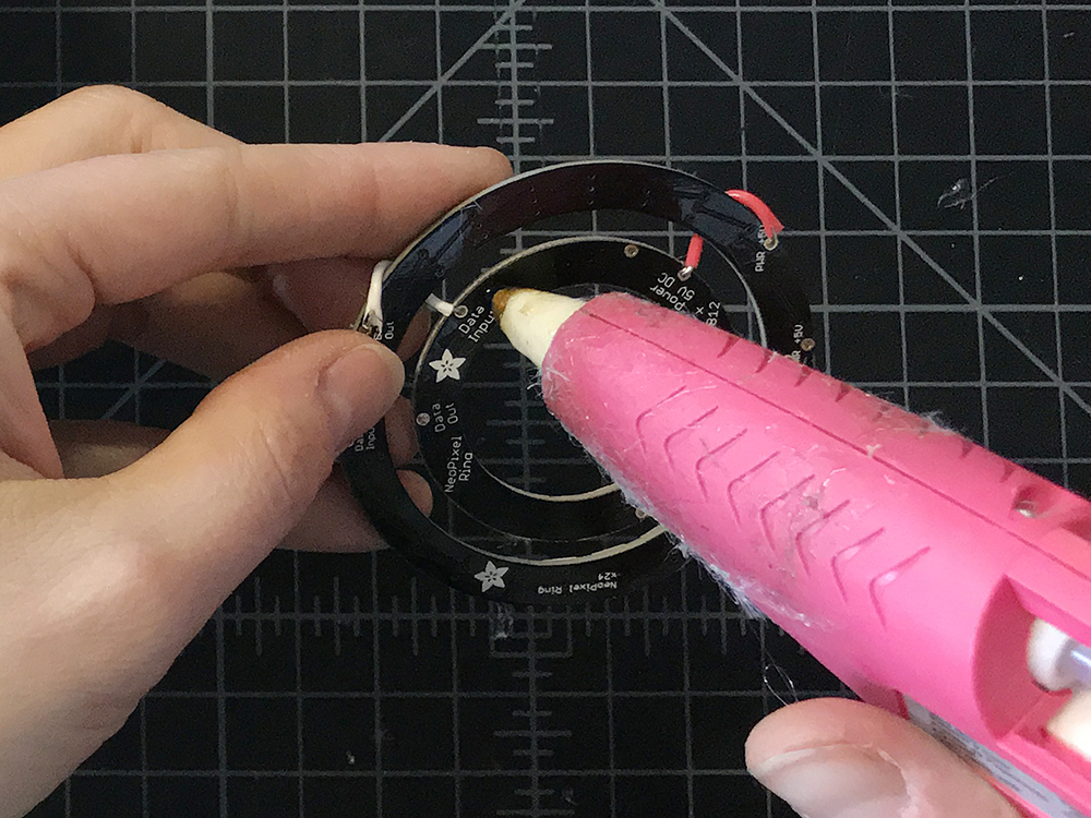
STEP 19:
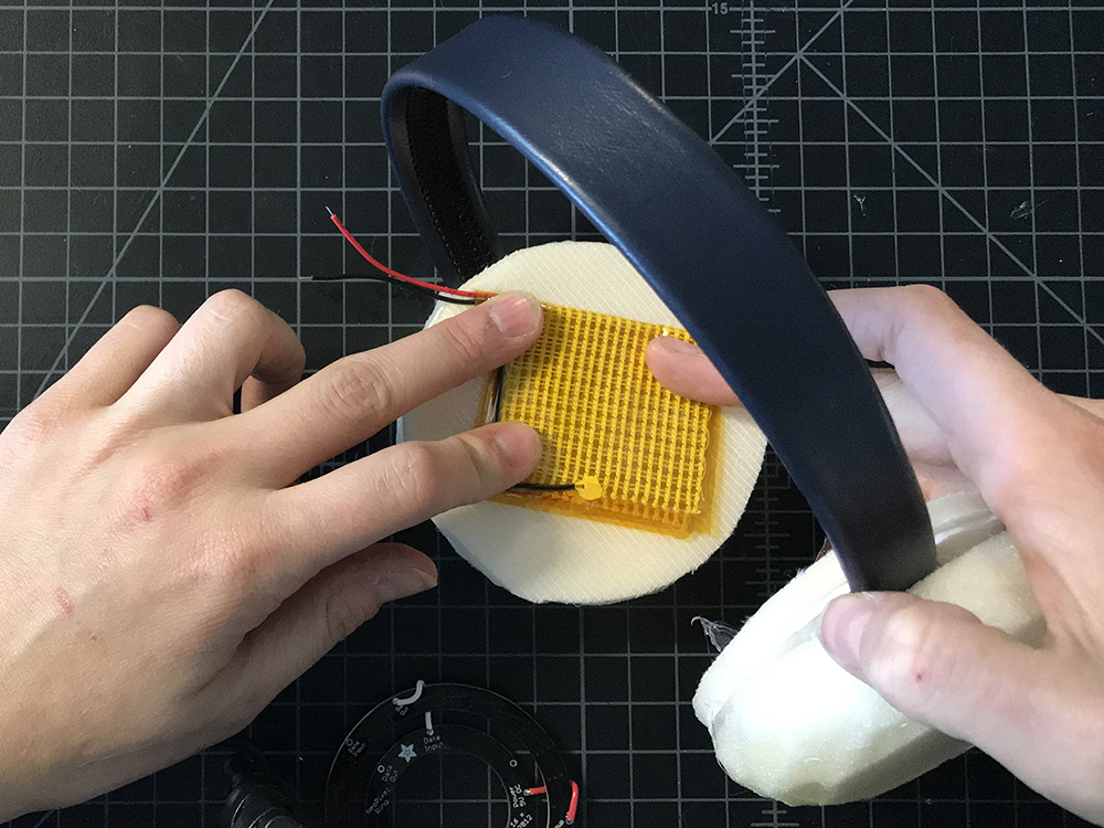
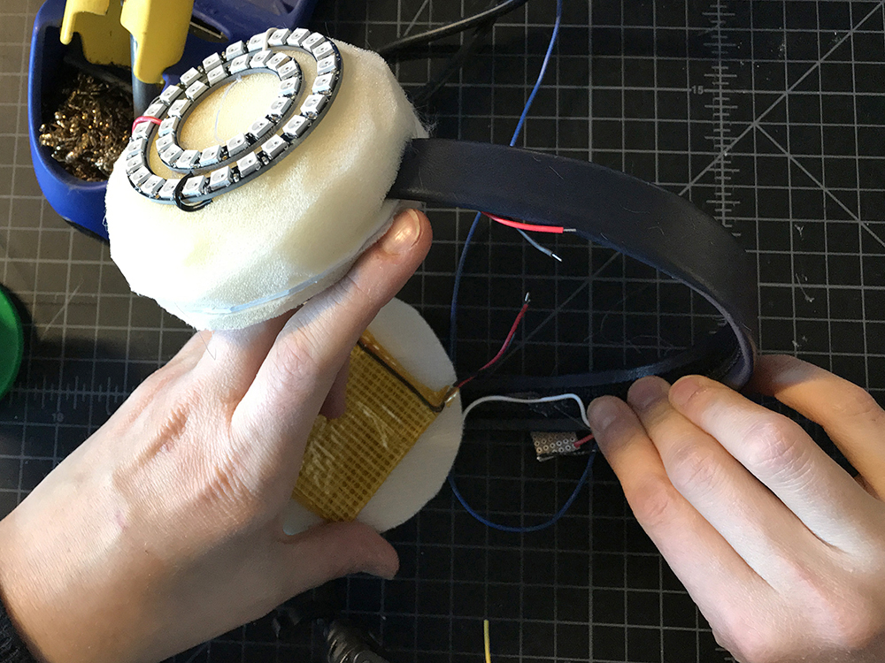
Add hot glue to the back of the smaller Neopixel ring.
STEP 20:
Place rings on top of the foam dome. Repeat with the second set of rings on the opposite side.
STEP 21:
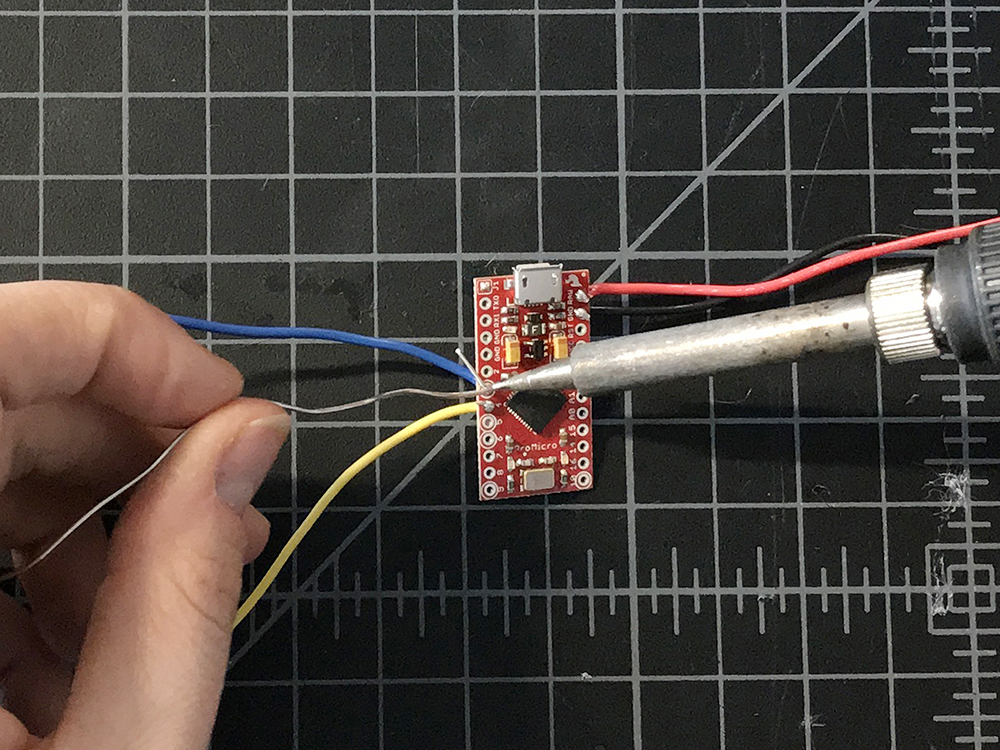
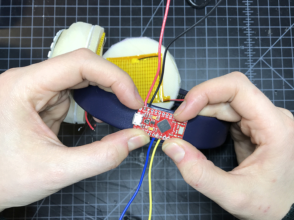
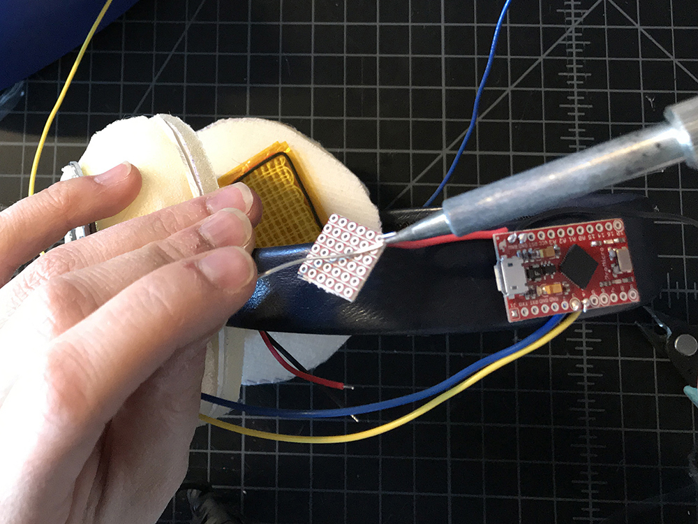
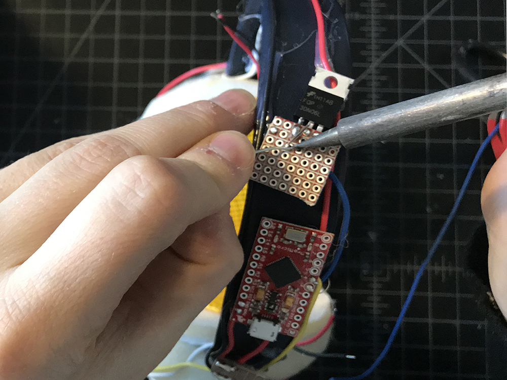
Solder medium length wire leads to Raw, GND, Pin 3 and Pin 4 on your Pro Micro.
STEP 22:
Place a small amount of hot glue to the back of the Pro Micro and then place it on the headband off to the side.
Soldering It Together
Now that all of our parts are in place, let's begin to solder the circuit together.
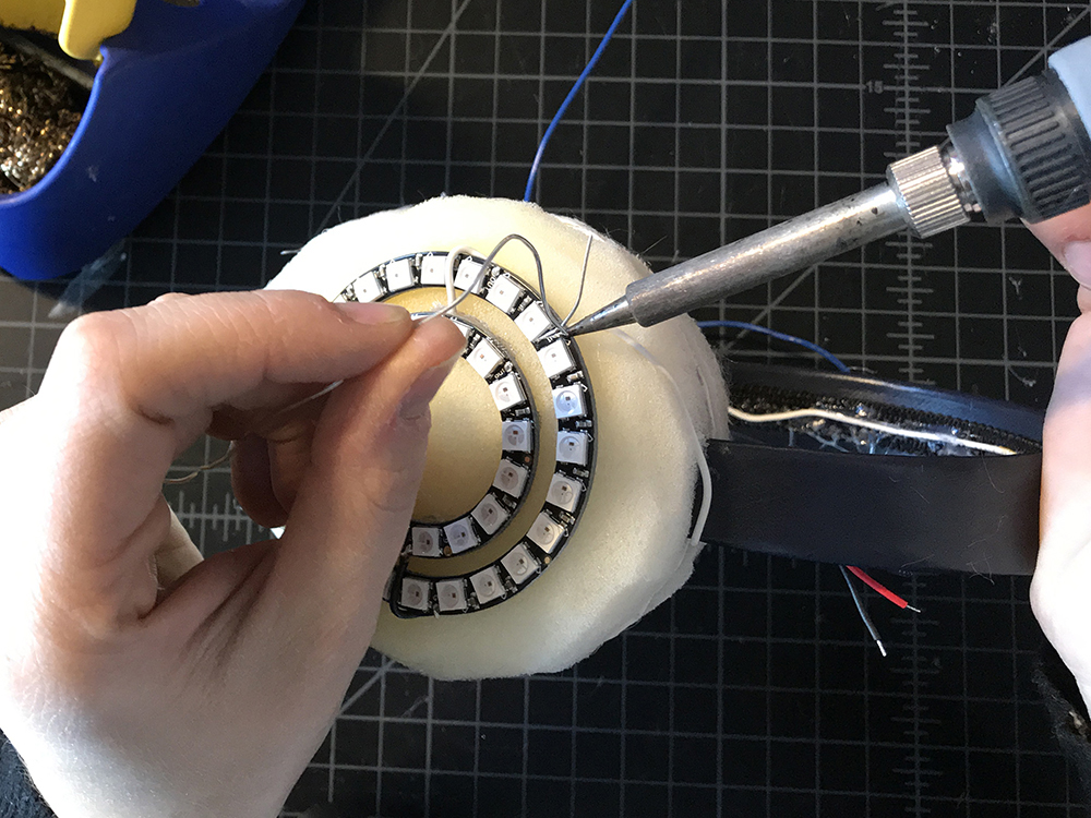
STEP 23:
Take a long piece of hook up wire and solder one end to DOUT of one of your smaller NeoPixel Rings.
STEP 24:
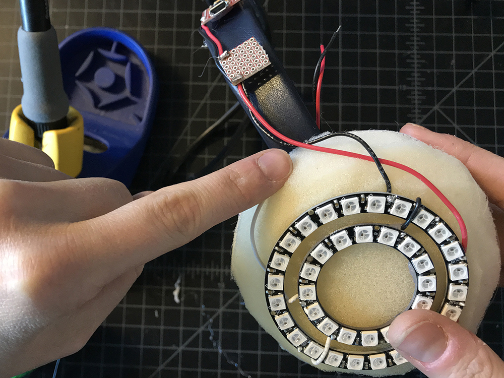
Lead it along the bottom edge of the headband, hot gluing it down along the way until you make it to the opposite side.
STEP 25:
Solder the other end to DIN of the larger ring on the opposite side. This in effect created one long LED strand of 80x WS2812 addressable LEDs.
STEP 26:
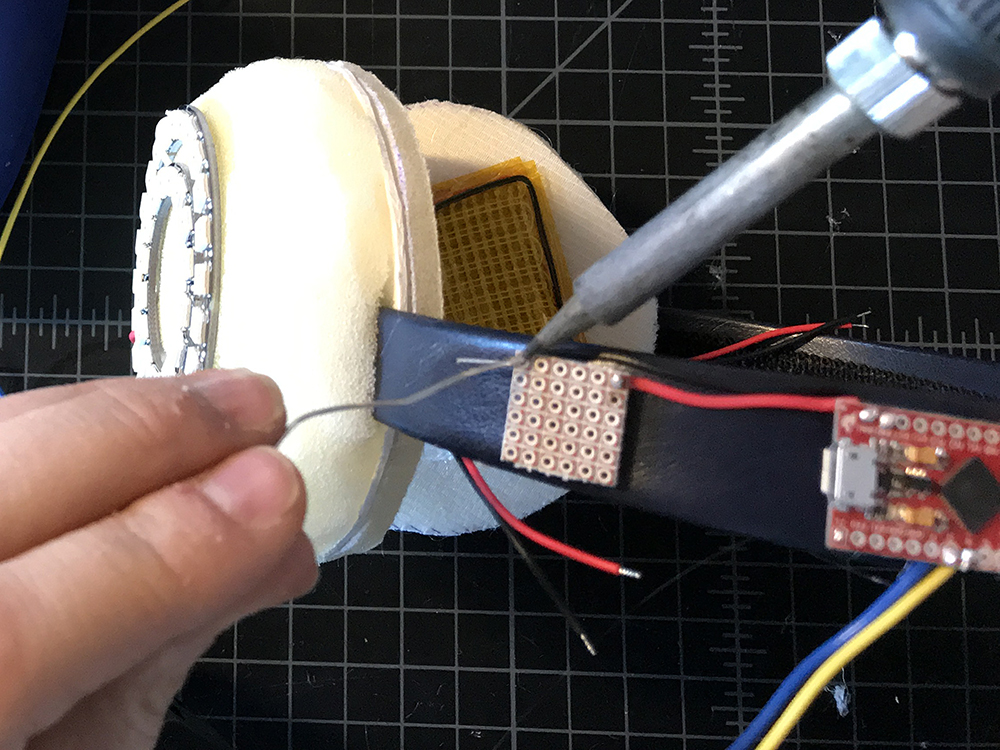
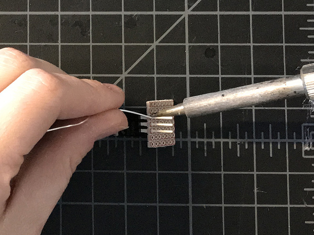
Cut the wire lead connected to Raw on the microcontroller down to about 1.5" - 2". Solder the free end to the corner of a piece of protoboard that is no wider than the headband. We will call this our Raw extension, and moving forward all connection to Raw will be made on this protoboard.
STEP 27:
Repeat step 26 for the GND wire lead. Make sure to solder it to the opposite end of the protoboard, leaving physical space between the two connections. We will call this our GND extension, and moving forward all connection to GND will be made on this protoboard.
STEP 28:
Solder a red wire lead to the Raw extension on the protoboard, and a black one to the GND extension. Take the red wire and solder it to VCC on one of the large Neopixel Rings. Take the black wire and solder it to GND on one of the large NeoPixel rings. Repeat for the second large ring on the opposite side.
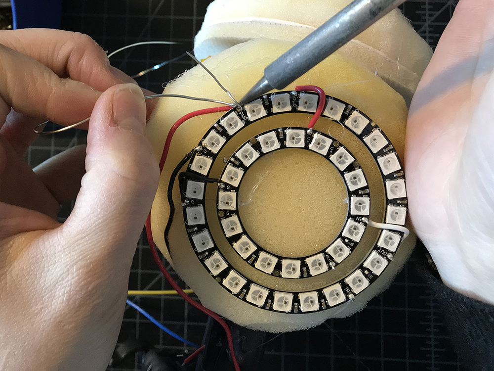
While you are doing this, make sure to bend your wires to fit the form of the earmuffs.
STEP 29:
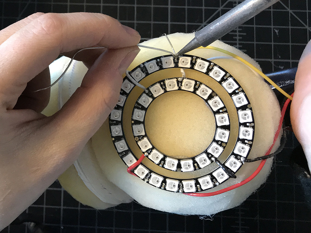
Find the wire lead connected to pin 4.

Solder this wire to the remaining DIN on your NeoPixel Ring. As we have soldered the two sides together, there should only be on DIN left for you to use.
STEP 30:
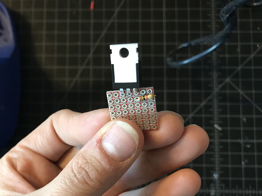
Cut a second small piece of protoboard, also no wider than the headband width, and solder the transistor along one edge.
STEP 31:
Trim the excess leads with a diagonal cutter and then fold the transistor back so that it lies flat in a plane with the protoboard.
STEP 32:
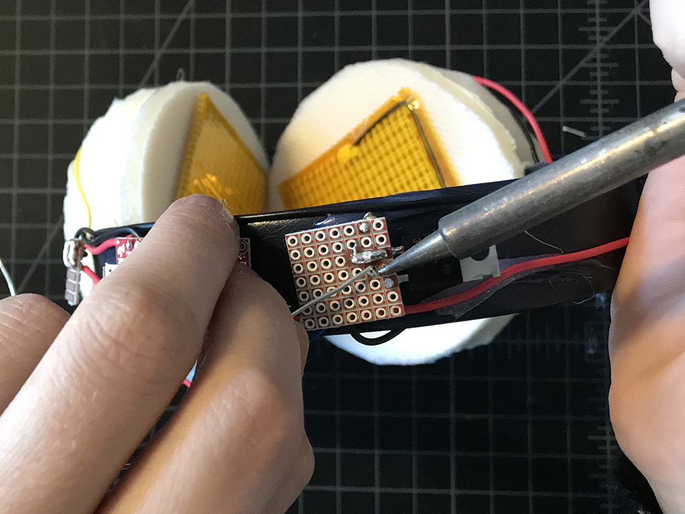
Solder a 10k resistor to the protoboard, connecting one end to the Gain (G) lead of the transistor and the other to a solder pad off to the side. Then use a jumper wire to solder the second side of the resistor to the GND extension.
STEP 33:
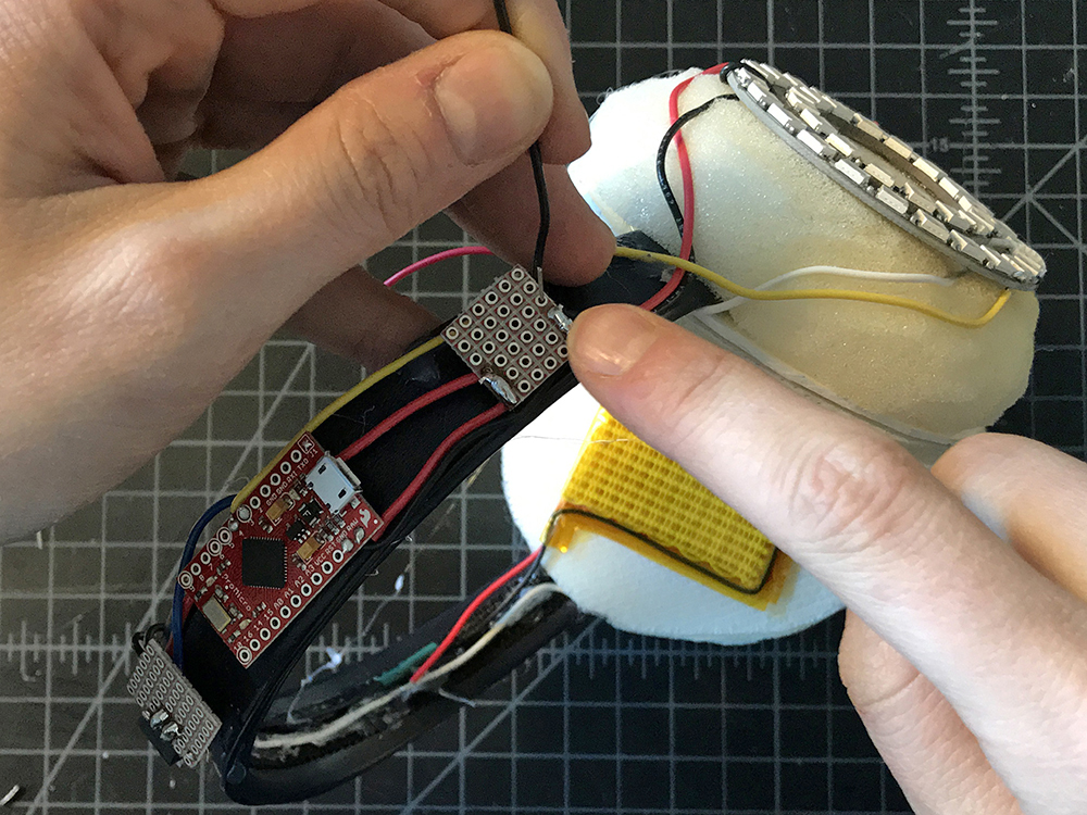
Holding the transistor protoboard to the headband with your thumb, solder the wire lead connected to pin 3 on the microcontroller to the same Gain (G) lead as the resistor on the transistor.
STEP 34:
Take two medium pieces of red wire and two medium pieces of black wire. Solder each red wire to the red leads on the heating pads, and each black wire to the black leads on each heating pad, in essence fabricating longer leads for the heating pads.

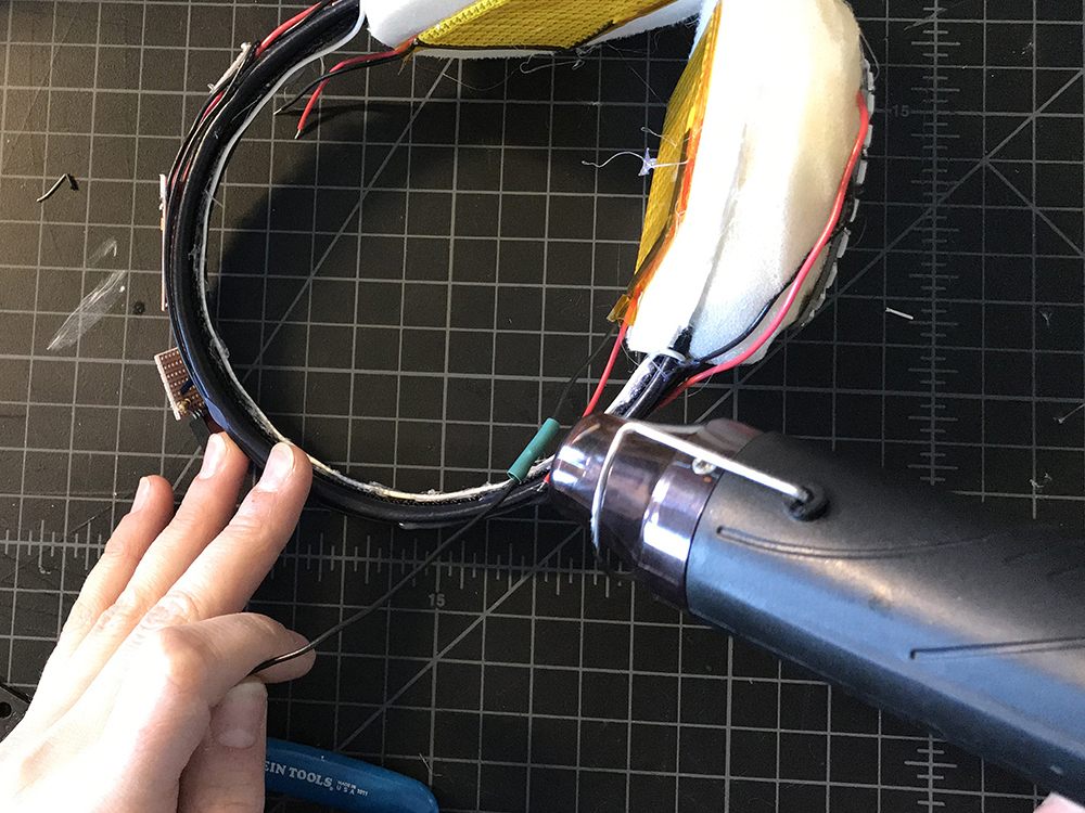
STEP 35:
Place a small piece of heat shrink over each new connection and then use the heat gun to secure it around the soldered connections.
STEP 36:
Take both black leads from the heating pads and solder them to the middle lead on your transistor - also known as the Drain (D).
STEP 37:
Grab a medium black length wire and solder one end to the GND extension on the first protoboard.
STEP 38:
Solder the second end of that wire to the Source (S) or rightmost lead on the transistor.

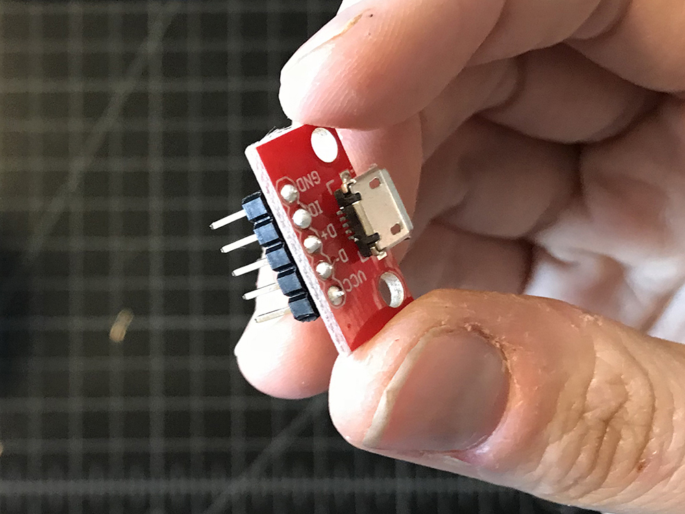
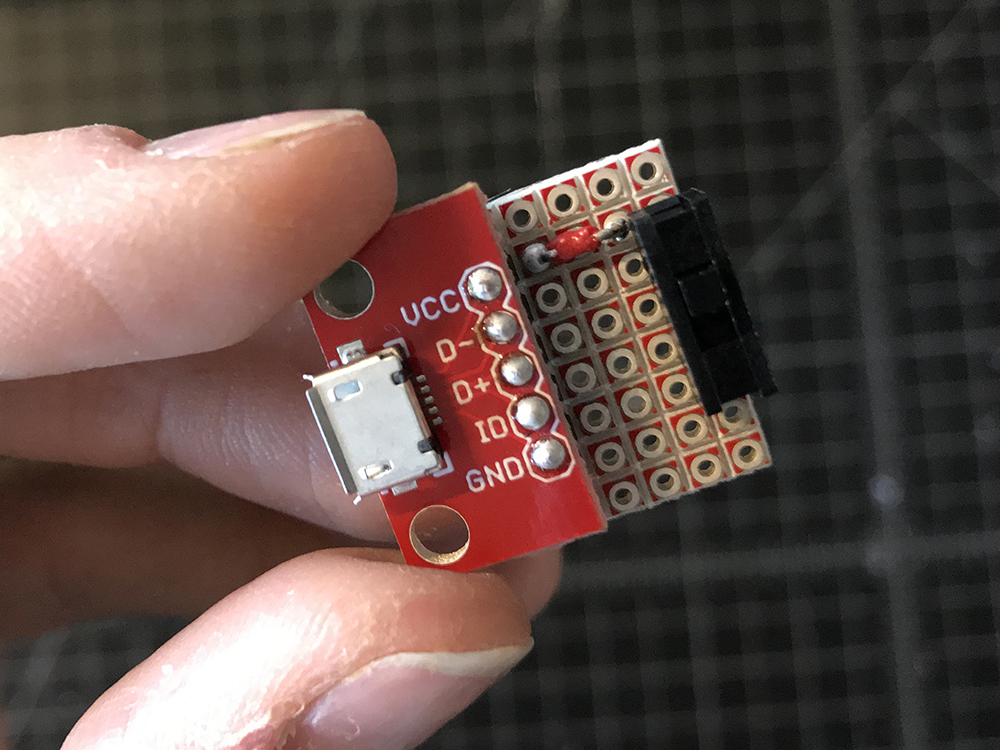
STEP 39:
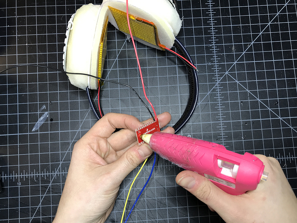
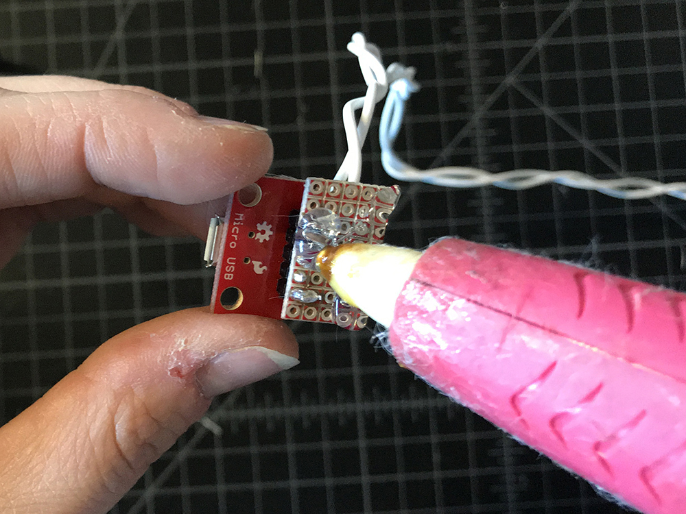
Solder header pins to your USB breakout.
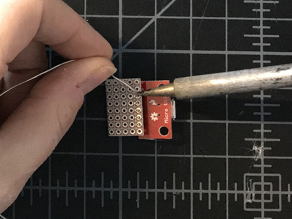
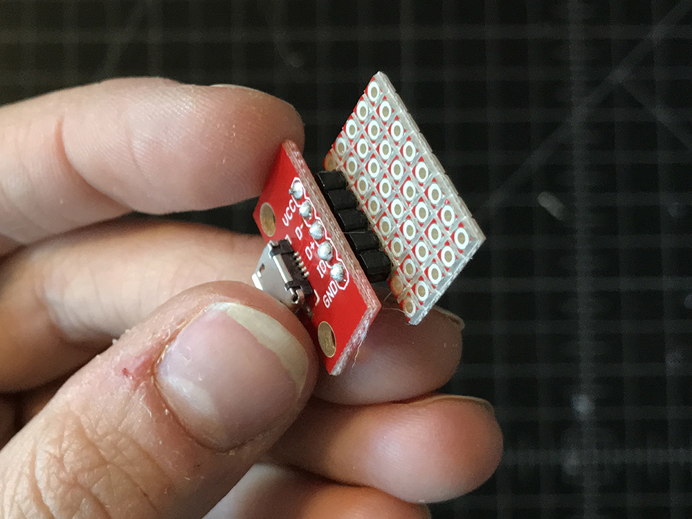
STEP 40:
Cut a third piece of protoboard slightly wider than your USB breakout, and solder the other end of the header pins to one edge.
STEP 41:
Solder the switch to the opposite edge of the protoboard.
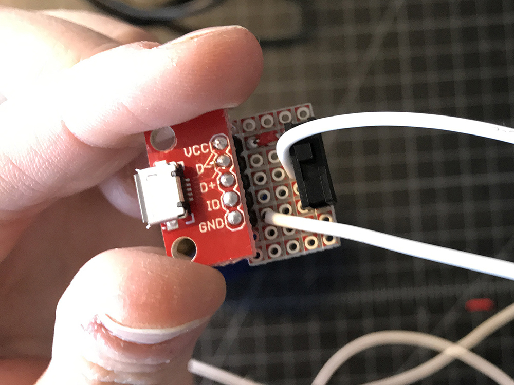
STEP 42:
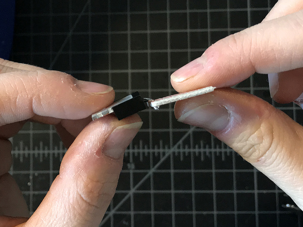
Use a very small piece of wire to connect VCC on your breakout to either the leg on the rightmost or leftmost of the switch. It does not matter which.
STEP 43:
Cut two long pieces of silicone wire in white. These should be long enough to reach from the crown of your head to your pants pocket.
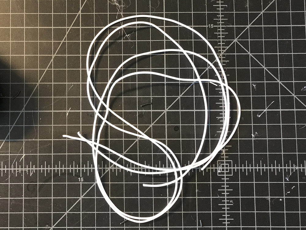
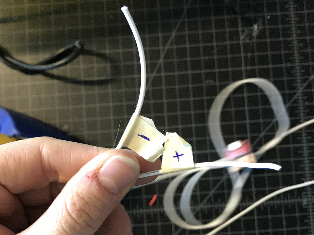
STEP 44:
Solder one wire to GND of the USB breakout, and the other to the middle lead of the switch. Label these right away with masking tape. The GND wire should be '-' and the Switch wire '+'.
STEP 45:
Twist the silicone wires lightly, the solder the '+' silicone lead to the Raw extension and the '-' silicone lead to the GND extension.
STEP 46:
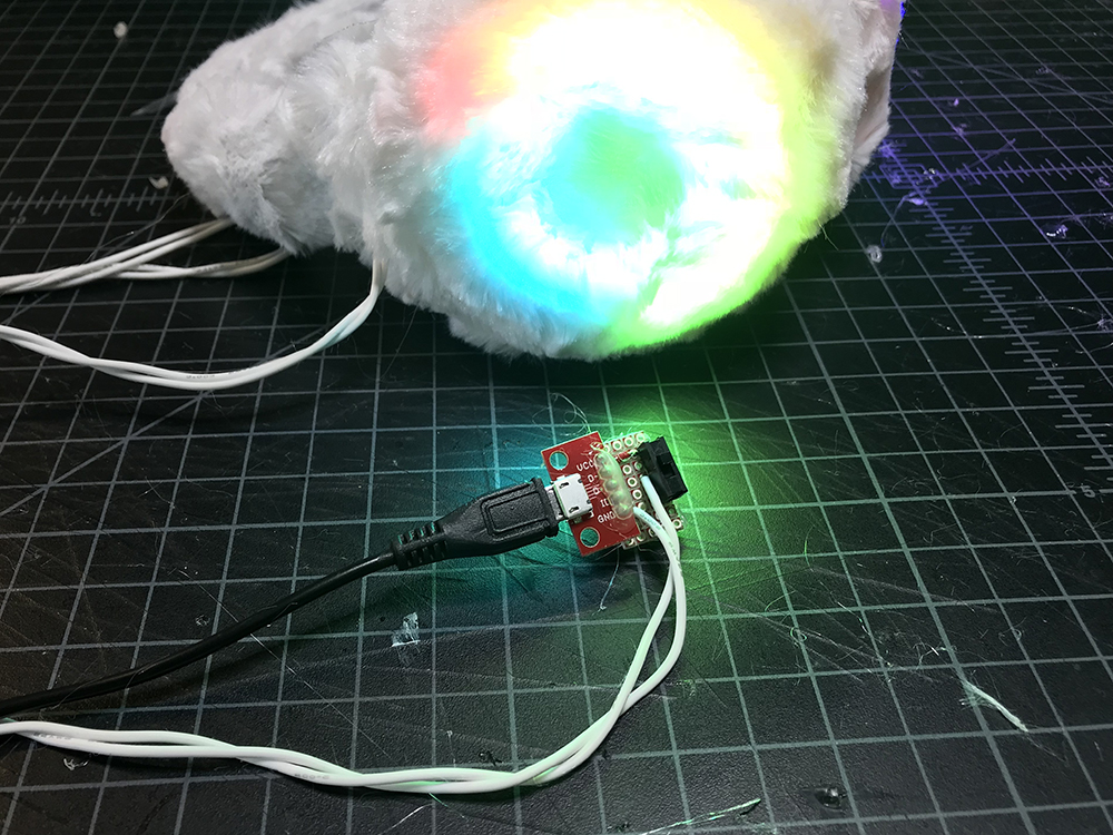
Plug the battery pack into the USB port and switch your project on to test. This is to make sure that the solder joints are strong and that there are no shorts.
STEP 47:
Add hot glue to the bottom of the protoboard for insulation.
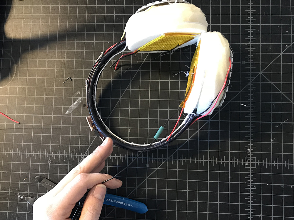
Completing the Enclosure
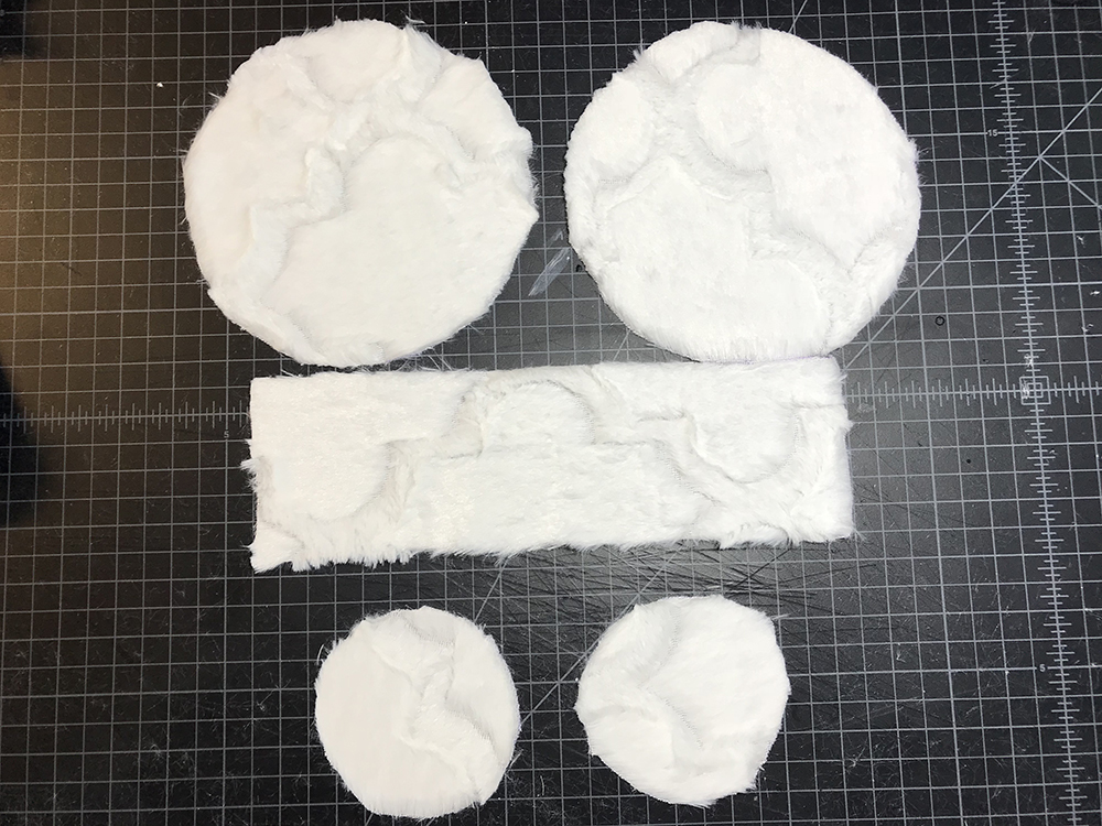
STEP 48:
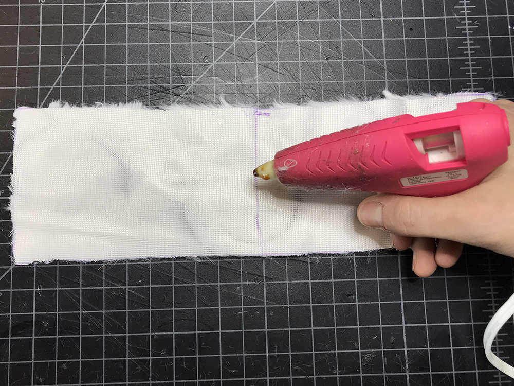
Grab both of the circles you cut from the template in Step 1. On the backside of your fabric, trace the large circle twice and the small circle twice. Then use a ruler to trace a 10.5" x 3.5" rectangle. Cut these out.
STEP 49:
Find the center of the rectangle piece of fabric on the backside by folding it in half and marking it. Then add a small dab of hot glue.
STEP 50:
Place the top and center most point of your headband on top of the hot glue.
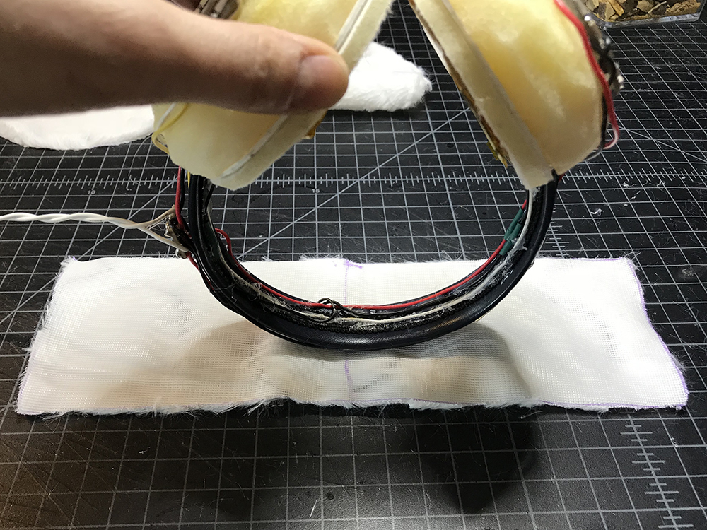
STEP 51:
Continue to hot glue the fabric rectangle over the headband.
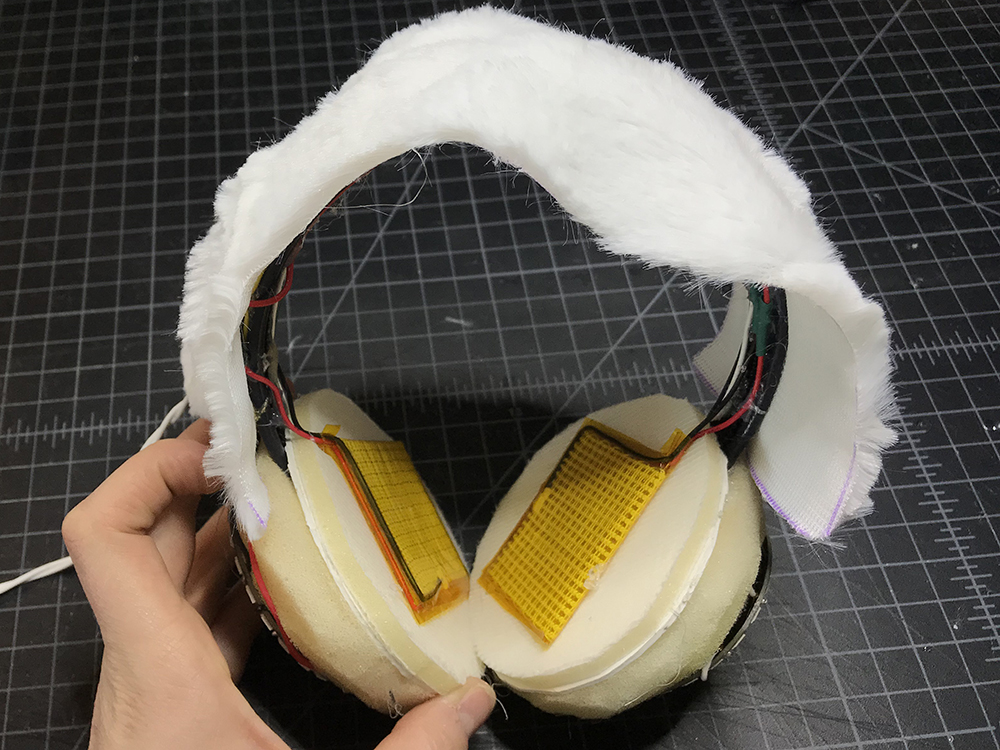
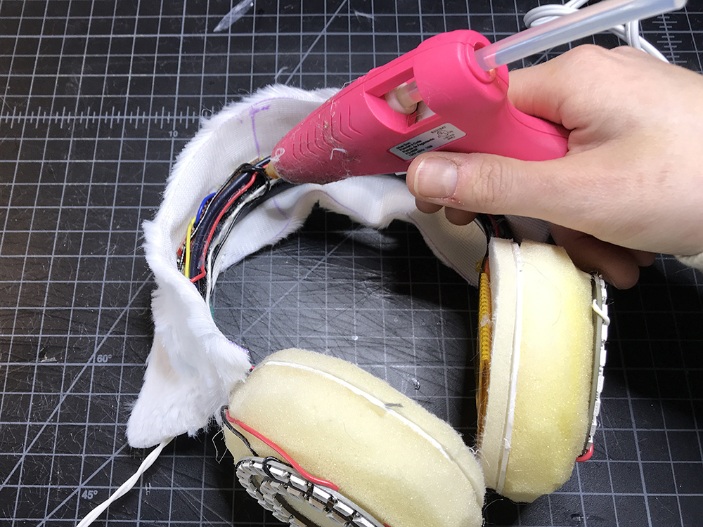
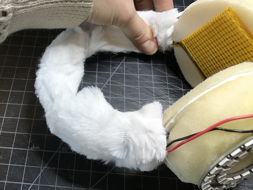
STEP 52:
Add hot glue on the bottom side of the headband along one edge and fold the fabric over, beginning to cover the bottom of the headband.
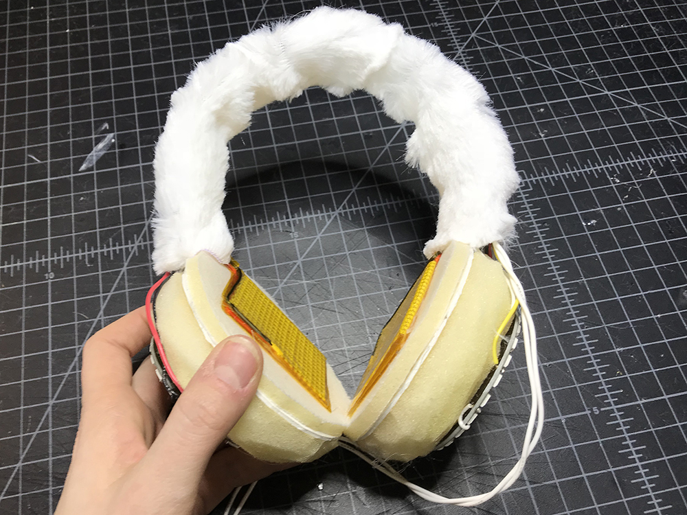
STEP 53:
Add hot glue to the free edge of the fabric on the backside and fold this over too. Once completed, your headband should be completely wrapped by fabric.
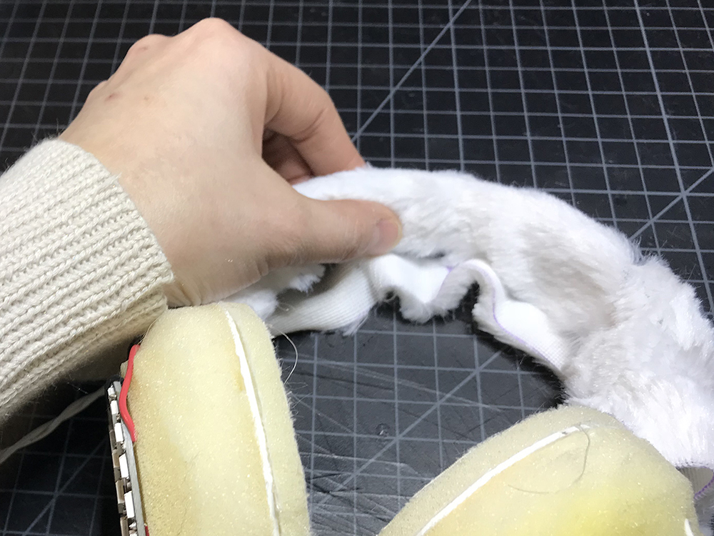
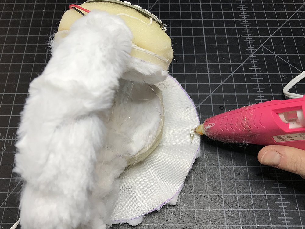
STEP 54:
Add hot glue around the edge of the interfacing on one side, and place a small circle of fabric on top. Repeat on the second side.
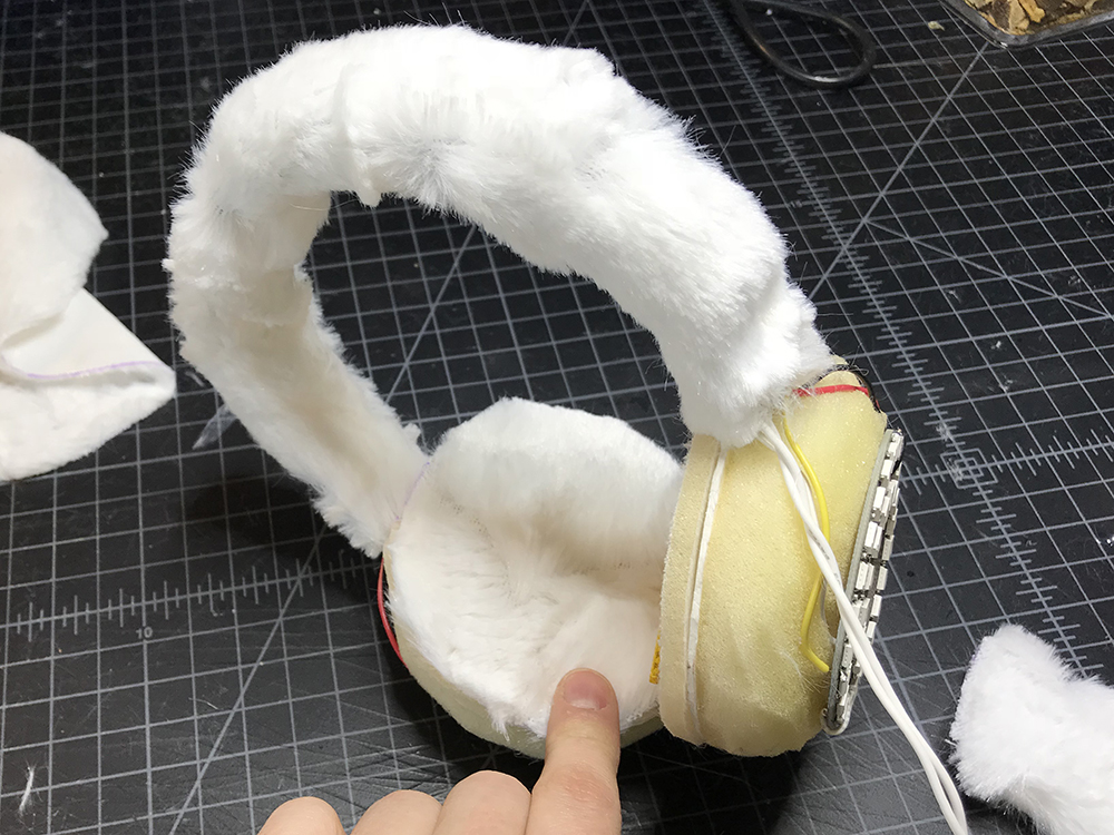
STEP 55:
Add some hot glue to the center of one of your foam domes, and then drape one of the larger circles of fabric on top, placing it as centered as possible.


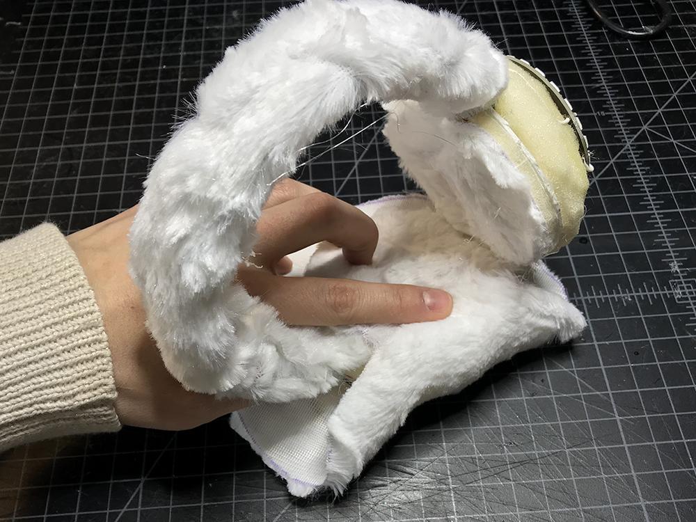
STEP 56:
Add hot glue to the free edges of the larger circle and begin to wrap it around the dome until it is completely wrapped.
STEP 57:
Plug in your power supply and turn the switch on!
Resources and Going Further
Looking for another project? Check out these similar projects for inspiration!