Displaying Your Coordinates with a GPS Module
Hardware Hookup
Technically, we only have one component to actually solder - the button switch. Truth be told, you could just use some alligator clips and not even need an iron. We have other colors, but I have a bias to green and I really liked the strength and feel of the metal momentary switch. When we solder the connections to jumper wires that fit the headers on the RedBoard, I’m assuming that you’ve developed some skills soldering. If not, that’s fine. We have a tutorial for that as well. Feel free to head over there and then put those wizard skills to work!
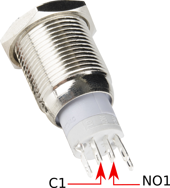
If you are soldering, then you can follow my connections. There are many ways to use switches, but I went for a momentary digital low. That just means that when I push the button the voltage on the digital pin assigned will be down from 5 volts to 0 volts. On the bottom of the switch you'll see a '+' and a '-'. These are for the LED backlight, and those will go to 5V and GND respectively. When you angle the button and look at that bottom portion, you'll see a few pin indicators labeled 'C1', 'NC1', and 'NO1'. NC1 and NO1 stand for normally closed and normally open. We'll want to solder C1 and NO1. This combination will give us the digital low when we push the button.
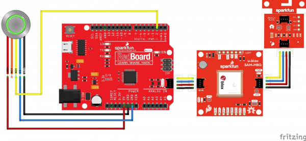
Attach the button pins to the RedBoard Qwiic as follows:
| Button Pin | RedBoard Pin |
|---|---|
| + | 5V |
| - | GND |
| C1 | GND |
| NO1 | Digital Pin 2 |
The next part for assembly is really simple. Just connect our boards together with our Qwiic cables, order doesn’t really matter!
Your final assembly should look something like this:
If you want to take the above in steps then you can hook up each component separately to the RedBoard to experiment. If you want to skip it and just throw caution to the wind, then please jump down to final code.

