Displaying Your Coordinates with a GPS Module
 Brandon J. Williams
 Introduction
What’s better than learning GPS? Learning it Qwiic-ly! Today we will be making a simple project to help get your feet wet with GPS. This project is quick and easy thanks to our Qwiic Connect System. The general idea is to push a button and see your latitude and longitude coordinates. We may be starting simple, but there is certainly room for more advanced users to modify and grow the project!
Software developers start with “Hello World!” and every hardware engineer remembers their first LED circuit, right? So let's fuse the ideas by creating a project that receives a GPS signal and outputs it to a screen for a user. Then we can bump it up by making it mobile. I’ve got just the thing in mind!
Required Materials
To follow along with this tutorial, you will need the following materials. You may not need everything, depending on what you have. Add it to your cart, read through the guide, and adjust the cart as necessary.
Suggested Reading
If you aren't familiar with the Qwiic system, we recommend reading here for an overview.
| Qwiic Connect System |
We would also recommend taking a look at the following tutorials if you aren't familiar with them.
I2C
Qwiic Micro OLED Hookup Guide
RedBoard Qwiic Hookup Guide
SparkFun GPS Breakout (ZOE-M8Q and SAM-M8Q) Hookup Guide
Hardware Overview
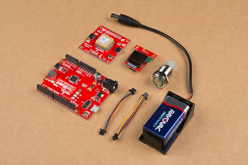
We’re using three large components, a 9V battery, and Qwiic cables. Let’s look into the bigger components first before we start.
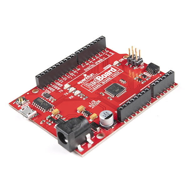
RedBoard Qwiic
First up, the brains of our project. This development board is an evolution on our classic RedBoard. No change to programming with Arduino, so software is still easy. However, this allows us to streamline Qwiic development without the need for a shield. If you have the classic RedBoard and still want to make this project, arm yourself and grab a shield!
Qwiic Micro OLED
We will read our coordinates using a simple OLED screen. Our product page describes this component best: “This version of the Micro OLED Breakout is exactly the size of its non-Qwiic sibling, featuring a screen that is 64 pixels wide and 48 pixels tall and measuring 0.66" across.” So we have small but powerful screen and that’s perfect for our purposes.
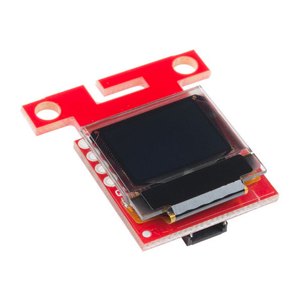
SparkFun Micro OLED Breakout (Qwiic)
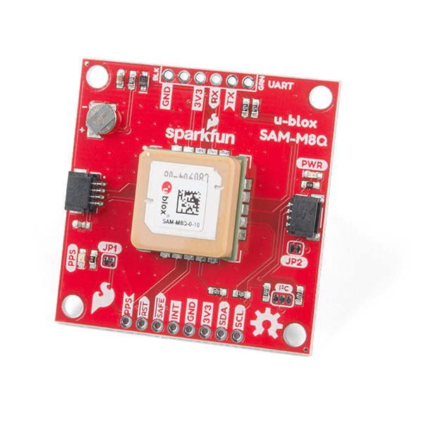
LCD-14532SAM-M8Q Chip Antenna GPS Breakout
Lastly, we will use a GPS module and we have one perfect for this occasion. This new GPS Breakout brings the ease, quality, and affordability from a great line of GPS modules from u-blox. The biggest feature is hot start and low lock time with a rechargeable coin cell battery. This means we have a powerful, inexpensive GPS that fits in a small space and will do all our talking with the satellites up above!
Hardware Hookup
Technically, we only have one component to actually solder - the button switch. Truth be told, you could just use some alligator clips and not even need an iron. We have other colors, but I have a bias to green and I really liked the strength and feel of the metal momentary switch. When we solder the connections to jumper wires that fit the headers on the RedBoard, I’m assuming that you’ve developed some skills soldering. If not, that’s fine. We have a tutorial for that as well. Feel free to head over there and then put those wizard skills to work!
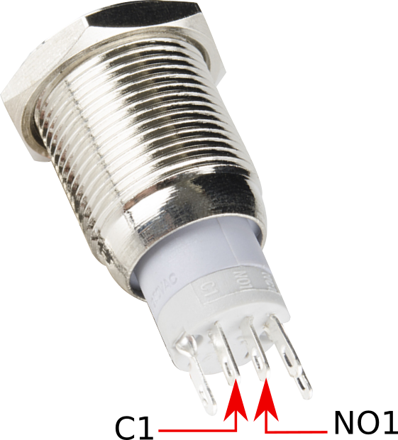
If you are soldering, then you can follow my connections. There are many ways to use switches, but I went for a momentary digital low. That just means that when I push the button the voltage on the digital pin assigned will be down from 5 volts to 0 volts. On the bottom of the switch you'll see a '+' and a '-'. These are for the LED backlight, and those will go to 5V and GND respectively. When you angle the button and look at that bottom portion, you'll see a few pin indicators labeled 'C1', 'NC1', and 'NO1'. NC1 and NO1 stand for normally closed and normally open. We'll want to solder C1 and NO1. This combination will give us the digital low when we push the button.
Attach the button pins to the RedBoard Qwiic as follows:
| Button Pin | RedBoard Pin |
|---|---|
| + | 5V |
| - | GND |
| C1 | GND |
| NO1 | Digital Pin 2 |
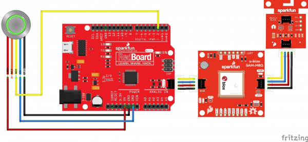
The next part for assembly is really simple. Just connect our boards together with our Qwiic cables, order doesn’t really matter!
Your final assembly should look something like this:
If you want to take the above in steps then you can hook up each component separately to the RedBoard to experiment. If you want to skip it and just throw caution to the wind, then please jump down to final code.
Software Setup
If this is your first time using Arduino, please review our tutorial on installing the Arduino IDE. If you have not previously installed an Arduino library, please check out our installation guide.
SparkFun Micro OLED library
First, you'll need to download and install the Sparkfun Micro OLED library. You can install the library via the Arduino Library Manager by searching 'SparkFun Micro OLED Breakout'. Alternatively, you can either grab the library from the GitHub repository or use the button below:
SparkFun U-blox Arduino Library
You will also need to install the Ublox library for the GPS unit. The SparkFun U-blox Arduino library can be downloaded with the Arduino library manager by searching 'SparkFun ublox GPS' or you can grab the zip here from the GitHub repository:
From the hookup guides, I hope you have a good understanding with how we’re setting this project up. We want to read a GPS location and output our latitude and longitude to the Micro OLED screen so we can see where we’re at. Sounds simple enough. So let’s start with our Qwiic Micro OLED Screen.
Example Code
Micro OLED Code
I’ve modified a snippet of code from our hookup guide for a small test of writing text to the OLED screen. Before it can be used, make sure you've installed the micro OLED library as listed in the Software Setup section above. Copy the code, paste it into the Arduino IDE, select the Arduino/Genuino Uno, and the COM port, and hit upload to test!
language:c
#include <Wire.h>  // Include Wire if you're using I2C
#include <SFE_MicroOLED.h>  // Include the SFE_MicroOLED library

//////////////////////////
// MicroOLED Definition //
//////////////////////////
//The library assumes a reset pin is necessary. The Qwiic OLED has RST hard-wired, so pick an arbitrarty IO pin that is not being used
#define PIN_RESET 9
//The DC_JUMPER is the I2C Address Select jumper. Set to 1 if the jumper is open (Default), or set to 0 if it's closed.
#define DC_JUMPER 1

//////////////////////////////////
// MicroOLED Object Declaration //
//////////////////////////////////
MicroOLED oled(PIN_RESET, DC_JUMPER);    // I2C declaration

void setup()
{
  delay(100);
  Wire.begin();
  oled.begin();
  oled.clear(ALL);
  oled.display();
  delay(1000);
  oled.clear(PAGE);
}

void loop(){
  printTest("Lat:-45.97760\nLong:42.91841", 0);
}

void printTest(String title, int font)
{
  oled.clear(PAGE);
  oled.setFontType(font);
  oled.setCursor(0,0);
  oled.print(title);
  oled.display();
  delay(1500);
  oled.clear(PAGE);
}
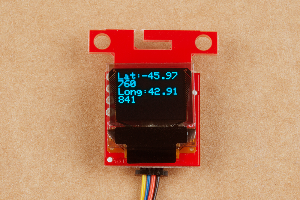
Once the library is installed we can simply compile and see a dummy text on our screen.
GPS Code
One done, two to go. Next we have our SAM-M8Q GPS module to test. I personally found the Example3_GetPosition code by Nathan Seidle to be the easiest and most convenient to experiment with. We find this sketch under File>Examples>Sparkfun u-Blox GNSS Arduino Library. Can’t find it? Make sure you've got the library for this GPS module installed as explained above in the Software Setup. It’s ok, I’ll wait. I may perhaps make some tea. Let me know when you’re ready and busting out data to the Arduino Serial Monitor. If that’s new to you, just verify and upload the code the board and hit that magnifying glass in the upper right hand corner. Set the baud rate to 115200, unless you want to see what our alien overlords have to say.
Final Code
If you're here, I take it that you’ve mastered the OLED Screen and SAM-M8Q module? Then I believe you’re ready! Seriously, this is the simple part. I blended the two previous sections of code to use the button to trigger a read from the GPS module and output the latitude and longitude to the OLED Screen. If you feel savvy, read through it and reverse engineer what I did so you can make glorious modifications! I say learn by breaking, master by rebuilding.
language:c
#include <Wire.h>
#include <SFE_MicroOLED.h>
#include "SparkFun_Ublox_Arduino_Library.h" //http://librarymanager/All#SparkFun_Ublox_GPS

#define PIN_RESET 9
#define DC_JUMPER 1

SFE_UBLOX_GPS myGPS;
MicroOLED oled(PIN_RESET, DC_JUMPER);

const int buttonPin = 2;
const int ledPin =  13;

int buttonState = 0;

void setup() {
  Wire.begin();

  delay(100);
  oled.begin();
  oled.clear(ALL);
  oled.display();
  delay(1000);
  oled.clear(PAGE);
  oled.display();

  oled.setFontType(0);
  oled.setCursor(0,0);

  pinMode(ledPin, OUTPUT);
  pinMode(buttonPin, INPUT_PULLUP);
}

void loop() {
    buttonState = digitalRead(buttonPin);
    if (buttonState == LOW){
      if (myGPS.begin() == false){
        oled.clear(PAGE);
        oled.print("No GPS");
        oled.display();
        delay(1500);
        oled.clear(PAGE);
        oled.display();
        oled.setCursor(0,0);
      }
      if(myGPS.begin() == true){
        myGPS.setI2COutput(COM_TYPE_UBX);
        myGPS.saveConfiguration();

        float latitude = myGPS.getLatitude();
        latitude = latitude / 10000000;

        float longitude = myGPS.getLongitude();
        longitude = longitude / 10000000;
      ////////////////////////////////////////////
      // Uncomment for altitude, add to output  //
      ////////////////////////////////////////////
      //   float altitude = myGPS.getAltitude();//
      ////////////////////////////////////////////

        oled.clear(PAGE);
        oled.print("Lat:");
        oled.print(latitude,6);
        oled.print("\nLong:");
        oled.print(longitude,6);
        oled.display();
        delay(10000);
        oled.clear(PAGE);
        oled.display();
        oled.setCursor(0,0);
      }
    }

}
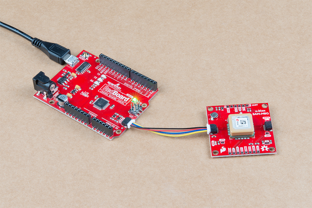
With everything connected, press the button to view your coordinates on the OLED! Instead of using your USB for power, connect a 9V battery to the RedBoard to go mobile!
Let's Wrap it Up
For myself, this project has a special purpose. I love to go fishing and I’m a nerd. So my usage for this project is to map my catches. When I make record breaking catch of unearthly magnitudes (okay most of my trophies are around 4 inches, but lets both just move on), I’ll take a photo and then safely release the little guy. What I’d like to do is geo-tag those catches by using the coordinates I write down from my gadget and then pin them to the pictures of my catches. This way I can look back at where my biggest catches were so I can go there again, or just make some hypothesis as to the health of the lake.
Take the next step
Now that you can literally find your location on earth with a push of a button let's do something more useful and put our locations on a map. With just a few different pieces of hardware, the following tutorial teaches you how to do just that.
GPS Geo-Mapping at the Push of a Button
Resources and Going Further
In case you'd like to delve a little deeper into the bits and bobs we've used in this tutorial, check out some of the links below:
SparkFun RedBoard Qwiic
- RedBoard Qwiic Hookup Guide
- Schematic (PDF)
- Eagle Files (ZIP)
- CH340C Hookup Guide (for Drivers)
- GitHub Product Repository
- SFE Product Showcase
SparkFun Micro OLED Breakout (Qwiic)
- Micro OLED Hookup Guide
- Micro OLED (Qwiic) Schematic (PDF)
- Micro OLED (Qwiic) Eagle Files (ZIP)
- Micro OLED (Qwiic) Datasheet (PDF)
- SparkFun Micro OLED Library
- SparkFun Qwiic Micro OLED GitHub Repository
SparkFun GPS Breakout - Chip Antenna, SAM-M8Q (Qwiic)
- GPS Breakout - Chip Antenna, SAM-M8Q Hookup Guide
- Schematic (PDF)
- Eagle Files (ZIP)
- Datasheet (PDF)
- Integration Manual (PDF)
- u-blox Protocol Specification (PDF)
- u-center Software
- GitHub