Dialog ULP WiFi DA16200 R3 Shield Hookup Guide
 Alex the Giant, Ell C
Example 2: GPIO and LEDs
In this example, we're going to show you how to use the provided GPIO. Before we get started, let's get our hardware all hooked up.
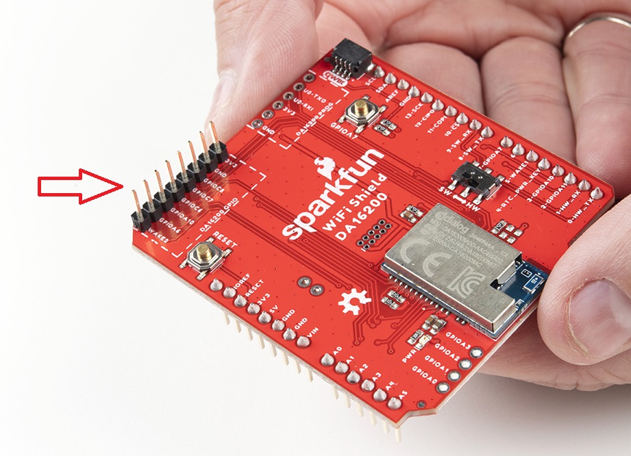
To start with, you'll need to solder headers to the DA16200 GPIO PTH pins.
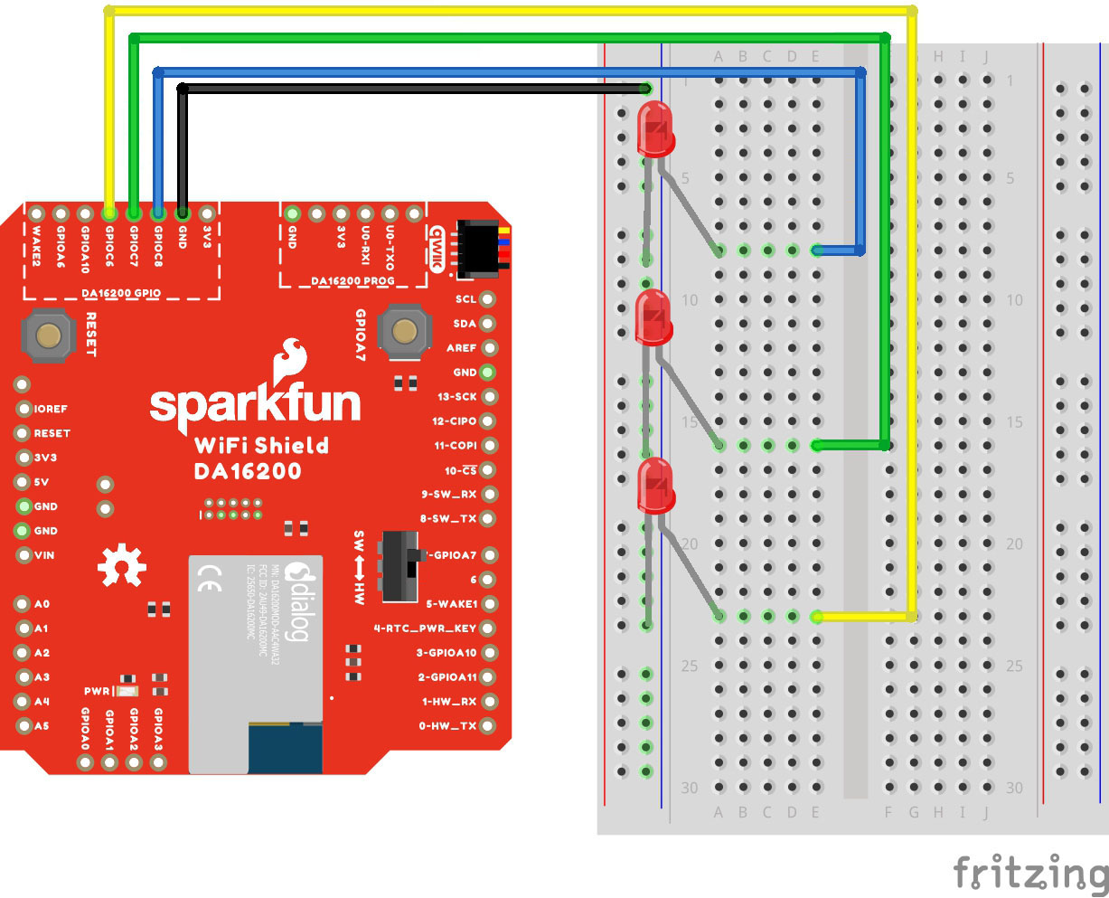
With your shield plugged into a SparkFun RedBoard (with 3.3V logic!!!), connect up your LEDs like so:
- Connect LED1 with current limiting resistor to GPIOC6
- Connect LED2 with current limiting resistor to GPIOC7
- Connect LED3 with current limiting resistor to GPIOC8
Make sure switch is in the "SW" position. Here's a Fritzing image to help you sort out the connections:
Our actual hookup looks like this:

Plug your board into your computer, and copy and paste the code below into a fresh Arduino sketch. Find the lines that define the SOFTWARE_SERIAL_BAUD and uncomment the line that contains the appropriate baud rate.
language:c
/******************************************************************************
  Example_02 Basic Communication

  Configure GPIOC6-8 as output pins, and toggle each LED individually.

  Development environment specifics:
  IDE: Arduino 1.8.13
  Hardware Platform: SparkFun RedBoard Qwiic (3.3V LOGIC!!!!)

  Hardware Connections:
  - Connect the shield to a 3.3V logic Arduino R3 board
  - Connect LED1 with current limiting resistor to GPIOC6
  - Connect LED2 with current limiting resistor to GPIOC7
  - Connect LED3 with current limiting resistor to GPIOC8
  - Make sure switch is in the "SW" position

  ARDUINO --> WiFi Shield --> External
  8       --> RX1
  9       --> TX1
  4       --> RTC_PWR_KEY
  -       --> GPIOC6      --> LED1
  -       --> GPIOC7      --> LED2
  -       --> GPIOC8      --> LED3
  3.3V    --> 3.3V
  GND     --> GND         --> GND

  This program is distributed in the hope that it will be useful,
  but WITHOUT ANY WARRANTY; without even the implied warranty of
  MERCHANTABILITY or FITNESS FOR A PARTICULAR PURPOSE. See the
  GNU General Public License for more details.

  You should have received a copy of the GNU General Public License
  along with this program.  If not, see <http://www.gnu.org/licenses/>.
******************************************************************************/

#include<SoftwareSerial.h>

#define RX1 8
#define TX1 9
#define RTC_PWR_KEY 4

//#define SOFTWARE_SERIAL_BAUD 115200
//#define SOFTWARE_SERIAL_BAUD 9600

SoftwareSerial WiFiSerial(RX1,TX1); //Configure SoftwareSerial

void setup() {
  Serial.begin(9600);
  WiFiSerial.begin(SOFTWARE_SERIAL_BAUD); //Set SoftwareSerial baud

  //Enable DA16200 Module RTC power block
  pinMode(RTC_PWR_KEY,OUTPUT);
  digitalWrite(RTC_PWR_KEY,HIGH);

  Serial.println("DA16200 AT Command Example: Controlling GPIO\n");

  //Listen for ready message ("+INIT:DONE")
  byte count = 0;
  String msg = "";
  while(count<20)
  {
    while(WiFiSerial.available())
    {
      msg += char(WiFiSerial.read());
    }
    if(msg.length() > 5) break;
    count++;
    delay(100);
  }
  msg = msg.substring(3,msg.length());

  if(msg.length()>5)
  {
    Serial.println("Expecting: \"INIT:DONE,(0 or 1)");
    Serial.println("Received: " + msg);
  }
  else
  {
    Serial.println("Failed to receive initialization message.\n" \
                   "Make sure you're using the correct baud rate.\n");
    while(1); //Unable to communcation with module, so don't move forward
  }


  WiFiSerial.println("AT+GPIOSTART=2,1C0,1"); //Configure GPIOC6, GPIOC7, GPIOC8 as outputs
}

void loop() {
  WiFiSerial.println("AT+GPIOWR=2,100,1"); //Set GPIOC8 high
  WiFiSerial.println("AT+GPIOWR=2,0C0,0"); //Set GPIOC6, GPIOC7 low
  delay(200);
  WiFiSerial.println("AT+GPIOWR=2,080,1"); //Set GPIOC7 high
  WiFiSerial.println("AT+GPIOWR=2,140,0"); //Set GPIOC6, GPIOC8 low
  delay(200);
  WiFiSerial.println("AT+GPIOWR=2,040,1"); //Set GPIOC6 high
  WiFiSerial.println("AT+GPIOWR=2,180,0"); //Set GPIOC7, GPIOC8 low
  delay(200);
}
Set your Board and Serial Port, and then upload the sketch to your Arduino. If you've hooked it all up right, you'll see the LEDs flash in order!