Creating a Humidor Control Box
 Paul Smith
Creating Tool Paths
I’m using a program called Visual Mill to create the tool paths for the box. A Tool Path is the area that the CNC machine will follow to cut out our box.
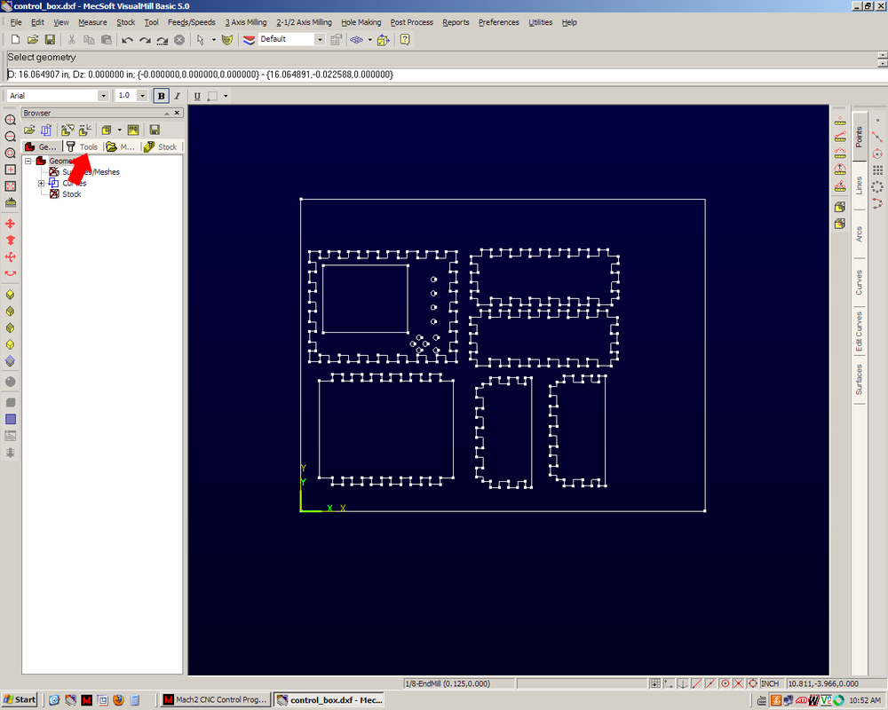
(1) First I will open the .dxf file that we saved. Then we need to choose the size of the endmill we are going to use.
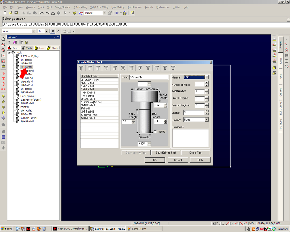
(2) I am going to use a 1/8” endmill. We can enter in the specific feature of our tool if we need to. Everything looks good so I’ll choose OK.
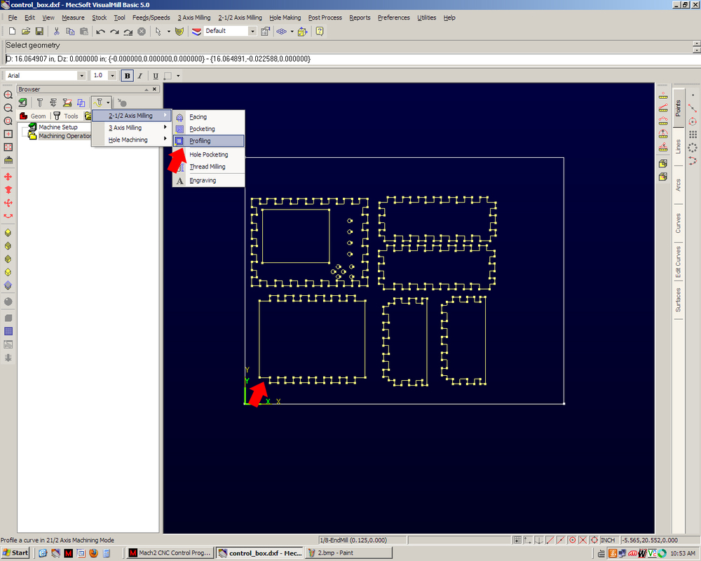
(3) Next, I’m going to select everything that we want to cut out. Selected lines turn yellow so the user can tell they are selected. We want to do a ‘Profile’ type cut. A profile cut will cut around the inside or outside of the part and leave the center intact.
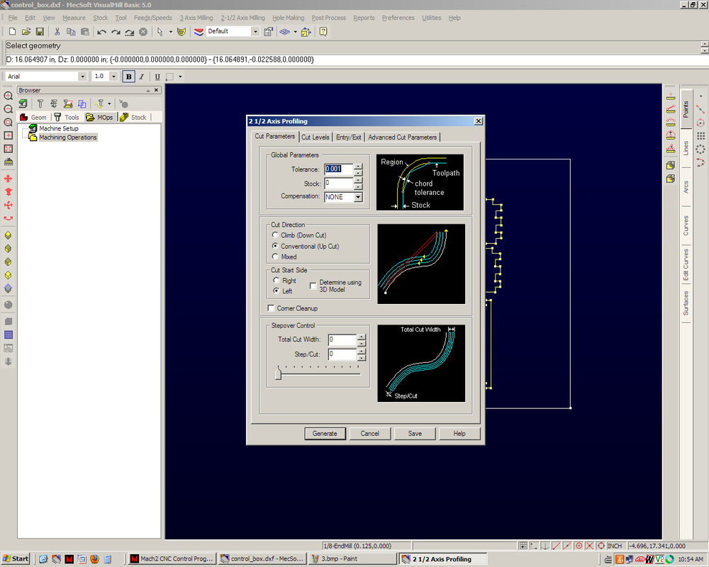
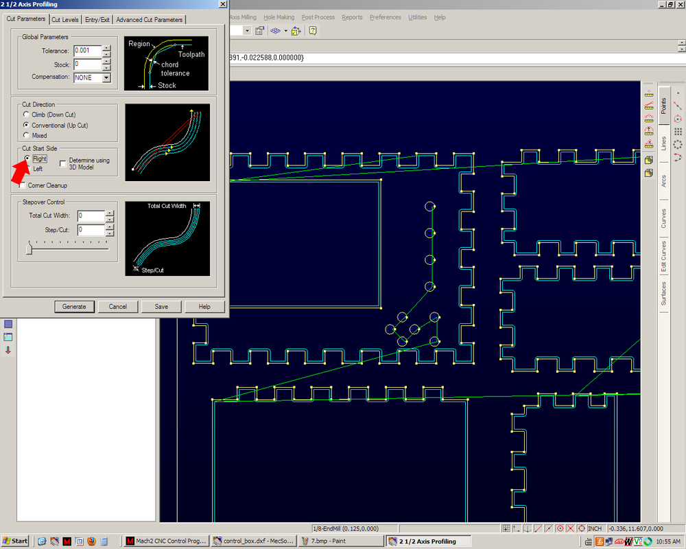
(4) Next we have to define a few options. We set the ‘Tolerance’ to .001 inches for good accuracy. ‘Cut Direction’ tells the computer to cut either clockwise or counter clockwise. For wood, a ‘Conventional’ cut works well. This will make the cutting edge on the tool spin into the material (think of a car tire spinning on pavement as the car slowly creeps forward) and keep the wood from peeling off instead of being cut. And lastly ‘Cut Start Side’ tells the computer to either cut on the inside or outside of the selected lines. We want to cut on the outside.
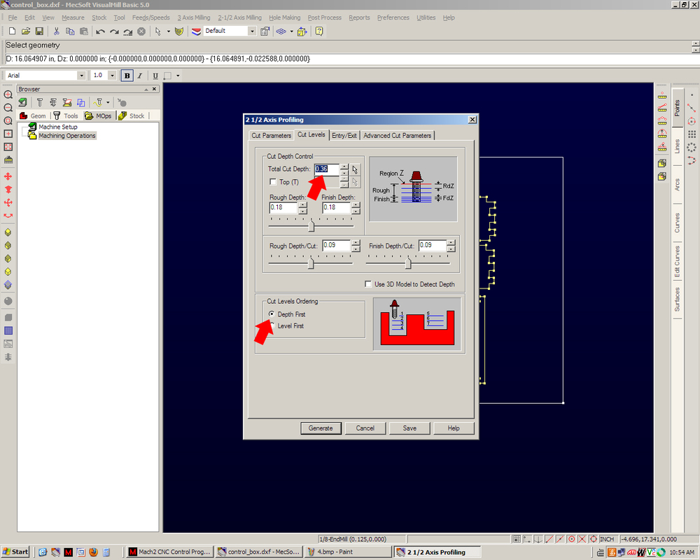
(5) On the next tab, we define how deep to cut. This is why earlier in the tutorial I said we only care about the 2D features of the parts. ‘Total Cut Depth’ tells the computer; yep you guessed it, how deep we want to cut. Since the wood is 0.35” thick, let’s go 0.36” to be sure. The ‘Rough Depth’ and ‘Finish Depth’ are ways to allow the user to very precisely control how much the CNC cuts off at a given time. Since we are cutting wood and not metal, we don’t need to worry too much about this. I have told the machine to cut in depths of 0.09”. That means it will take 4 passes to cut through.
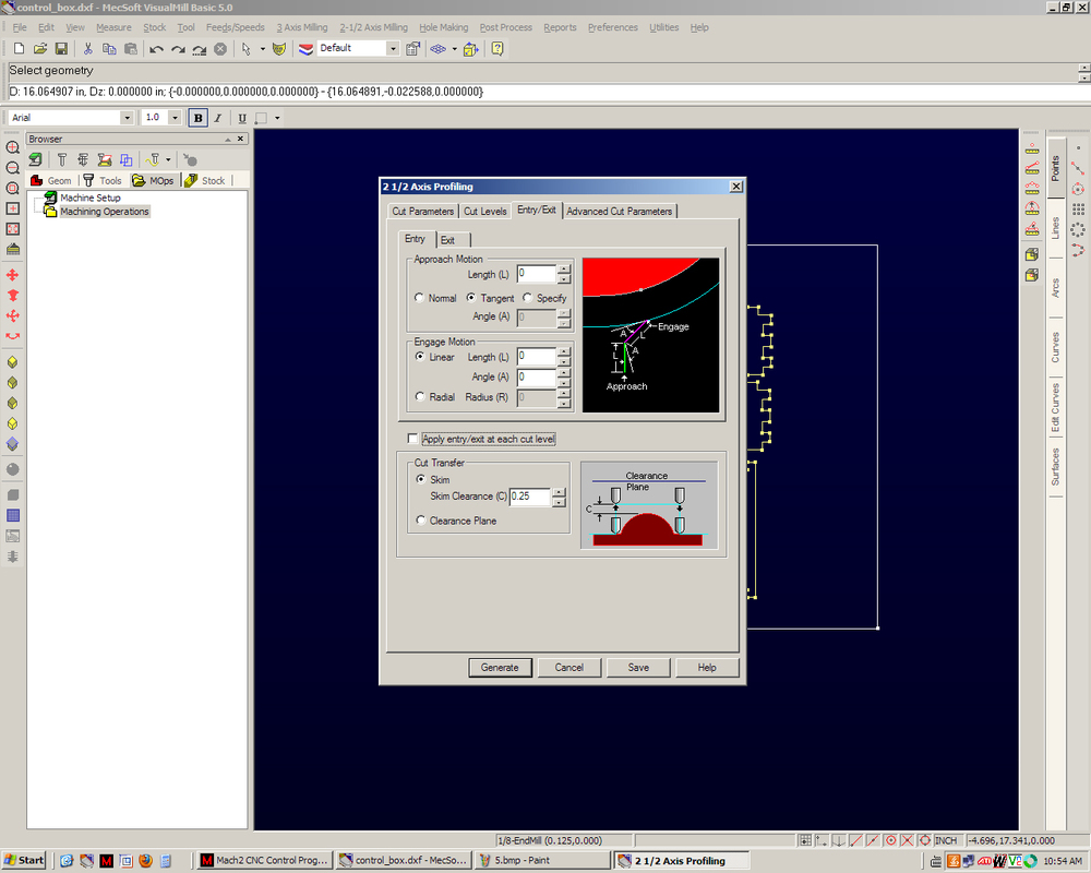
(6) Lastly for this options box are the approaches and engage motions. Because the bit I have is a center cutting bit, I can do what is called plunge cutting. Some bits can drill straight down (plunge) through the material, while others cannot. This is because the teeth of some cutters do not extend all the way to the center of the bit. However, these cutters can cut downwards at an angle of 45 degrees or so (called ramp cutting). We can set all of these values to zero. This will make the mill move into position and come straight down (plunge). Think of it like a bulldozer cutting into the ground (ramp cutting) versus an excavator digging in one spot (plunge cutting). The ‘Cut Transfer’ tells the CNC how high to lift up when moving from one spot to another. Since the plywood I’m using is somewhat warped, I’ll use 0.25” to be sure the machine does not accidently cut into a high spot in the wood when it is moving.
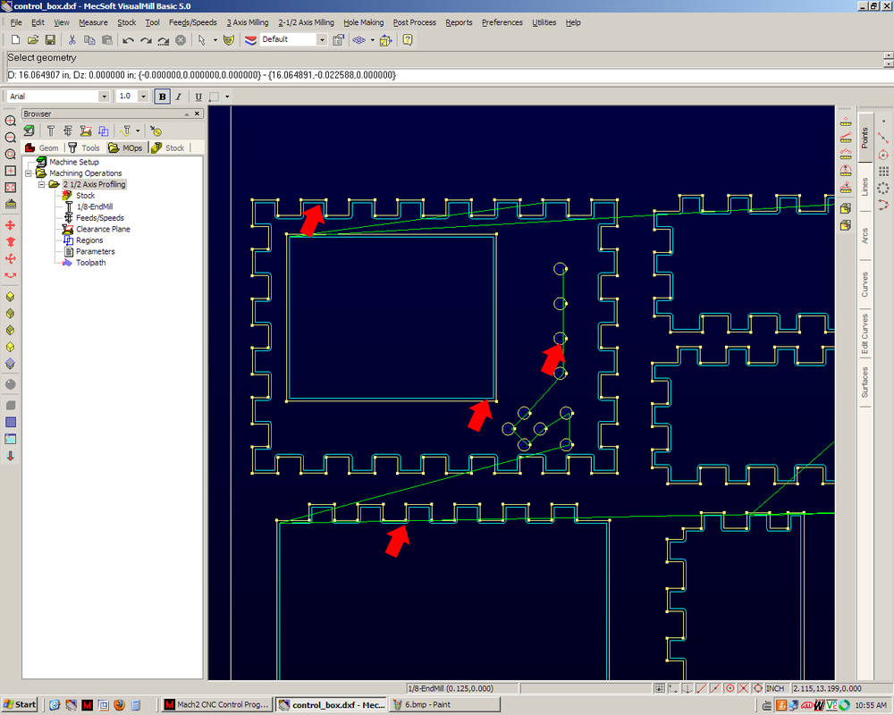
(7) Here we can see the tool path that has been created. If you look at the light blue colored lines you can see exactly where the endmill will be cutting. Hmm…wait a minute something doesn’t look right. The tool paths are on the inside of the part. If we run this, the panel will be too small!
(8) Easy fix! I’ll just edit the tool path and change the ‘Cut Start Side’ from Left to Right. This will generate the tool path on the correct side.
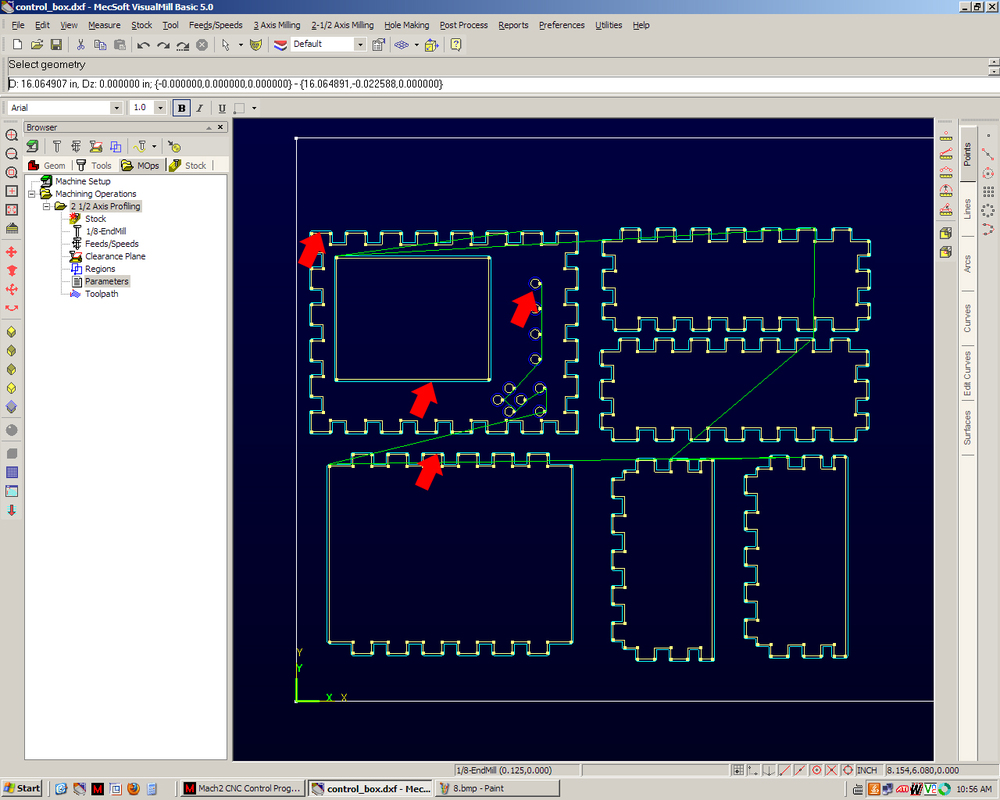
(9) Well that fixed the tool path for the panels. The cut marks are on the outside of the parts, which is what we want, but look at the LCD hole and button holes. Now they are on the outside. If we run the CNC now, they will be too big. So I guess we can't select everything at the same time. I’ll do one tool path for the outlines and one for the LCD + buttons.
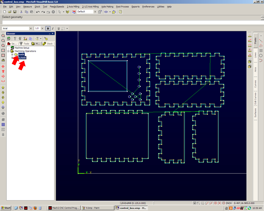
(10) There! Now everything looks as it should. The tool paths are on the outside of the exterior and inside the interior of the parts we want to cut out. Those green lines show where the machine will raise the bit and move to a new area.
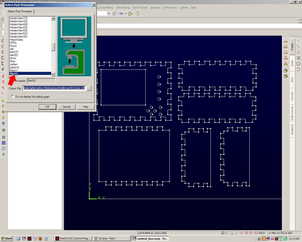
(11) Now we can export the tool paths as G code. G code is a format in which the computer tells the CNC where to move, one point at a time. The CNC moves in a straight line from one point to the next. As you can imagine for a circle, there are lots and lots of coordinates. The CNC controller program we use is called Mach2 so I’ll tell it to export for that.
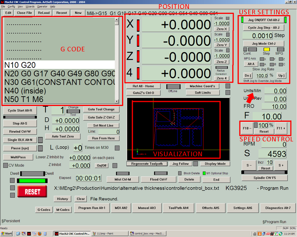
(12) We’re almost there now! This is Mach2 (see below), the program that reads the G code and sends the pulse commands to the CNC machine. I’ll explain the areas that I highlighted.
G CODE – This is the G code that is loaded into the program. N10 stands for Line Number 1. The G command tells the computer that we want to move the cutting bit to a certain location without cutting anything. A person could write an entire tool path in a text document if they wanted. It might take awhile though. Check out the wiki page for G code for a full list of all the codes!
POSITION – This is the current position of the center of the cutting bit as reported by the encoders on the CNC motors. X, Y, and Z are used here (we have a 3 axis CNC) but the 4th is not used.
USER SETTINGS – The Jog setting sets the speed limit for movement. If I want to manually move the CNC head to a certain spot, I can use the keyboard. If I tap an arrow key once, the CNC head will move a distance set in the Step box, in this case 0.001”. If I hold shift and press an arrow key, the CNC will move rapidly for as long as I hold the key. The ‘Slow Jog Rate’ limits the speed that the CNC can travel during the rapid movement.
Units/Min – This shows how fast the mill is traveling. When I cut wood, it will usually be around 15-30 inches per minute.
SPEED CONTROL – I didn’t show you this in Visual Mill, mostly because I hardly ever adjust it, but there are several speed setting for various things. We can set the speed at which material is cut, the speed at which the cutting bit goes up and down, the speed at which the CNC makes non-cutting movements, and other. The Speed Control lets us manually speed up or slow down all of these settings at the same time.
VISUALIZATION – This area shows 3 things. The lines in blue are what the mill is going to cut out, the green lines show where the mill has already cut (we haven't cut anything yet), and the yellow crosshairs show where the center of the endmill is at.
Some other features here are not available on our CNC. For example the Mist and Flood buttons control whether or not coolant is being sprayed on our part. We don’t have coolant on our CNC, so we don’t use this feature.