Creating a Humidor Control Box
 Paul Smith
3D Design
Our Production department came to me needing a humidor built. They needed a better system to re-humidify a select few of our boards that need it after coming out of the reflow oven.
I am a very visual person. I like to see exactly what I have designed and how it fits together before I start making it. By doing this, it is easy to see where my mistakes are and correct them.
For this project, I designed both the humidor and the control box for it. The control box allows our Production team to select which board they are placing in the humidor, iit will keep track of the time it has been in there. It also makes sure the humidity stays at the required percentage. I’m not going to cover much of the humidor in this tutorial, however. I laser cut acrylic and epoxied it together in the shape of a box. When it was dry, I added some weather strip to the front door to seal it and put caulk in all the joints to ensure it was air tight. Not too much going on there!
The control box was really fun to make. I decided to cut ‘teeth’ in all of the edges so it would fit together like a 3D puzzle. Here at Sparkfun, we use Creo Parametric 2.0 for our 3D modeling. Our Arduino and breadboard holder was designed with this along with all of our retail clamshell packaging. I learned this program in High School, and of all the modeling software I have used along the way, it is my favorite. Before I begin, I want to tell you that this tutorial only scratches the surface of the feature in Creo. I’m only going to cover a few main points and features, there is certainly more than one way to do all of this. Let’s start designing!
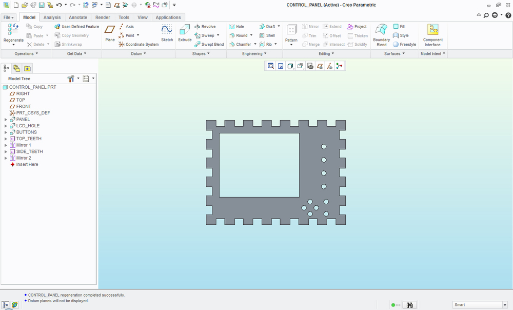
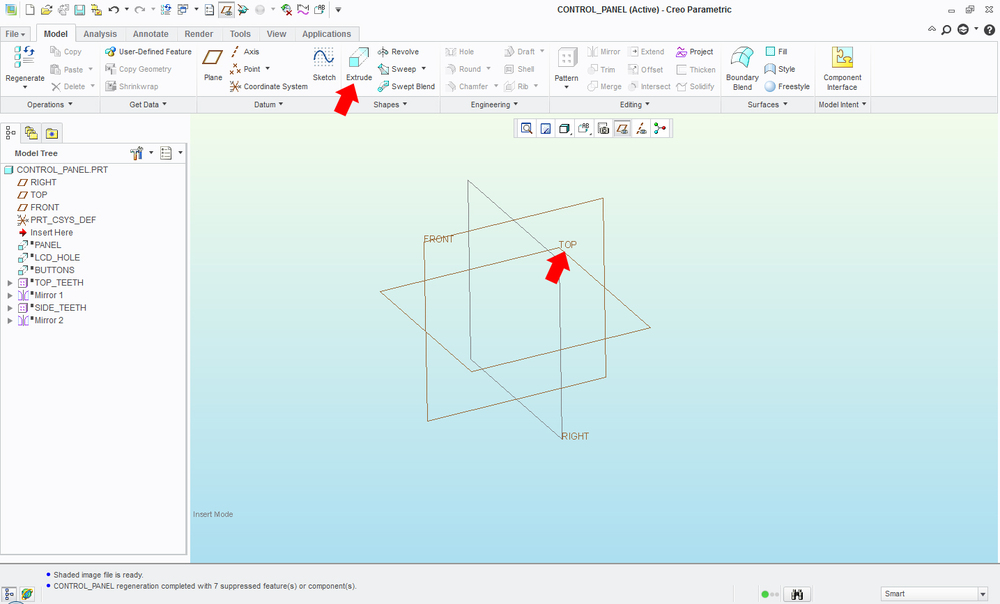
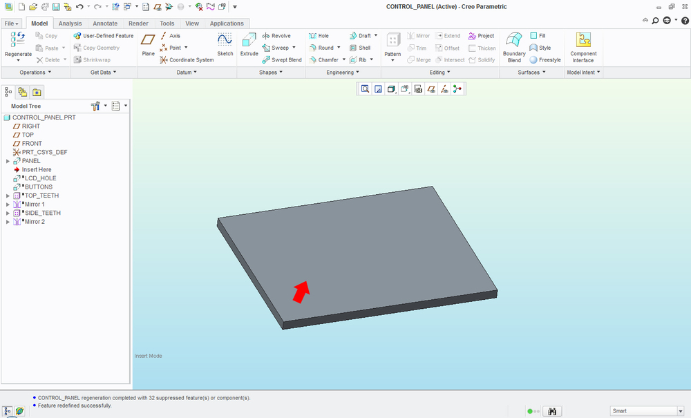
(1) In the picture below, we are going to start drawing the top panel for the control box. The area with the labels ‘FRONT’, ‘TOP’, and ‘RIGHT’ is our workspace. We want to choose one that accurately describes the surface that we want to draw. Since this panel will go on the top side of the box, I am going to select the ‘TOP’ plane. Probably the most used feature is the Extrude command. This allows us to create material (or remove it) in the shape we want. So to recap, we choose the ‘TOP’ plane and click Extrude.
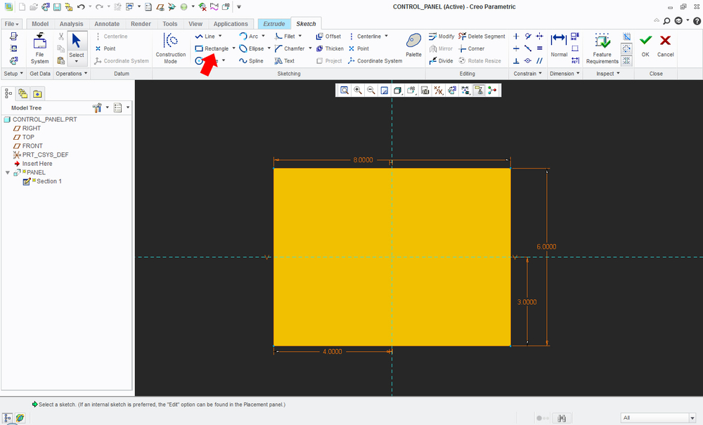
(2) This brings us to the Sketcher. The Sketcher is where we draw the features that we want. Using the Rectangle command, I will draw a rectangle. I decided that I wanted the panel to be 8 inches wide and 6 inches tall. The dimensions are added automatically when I draw the rectangle. All I have to do it change them to what I want. Once they are correct, I click OK.
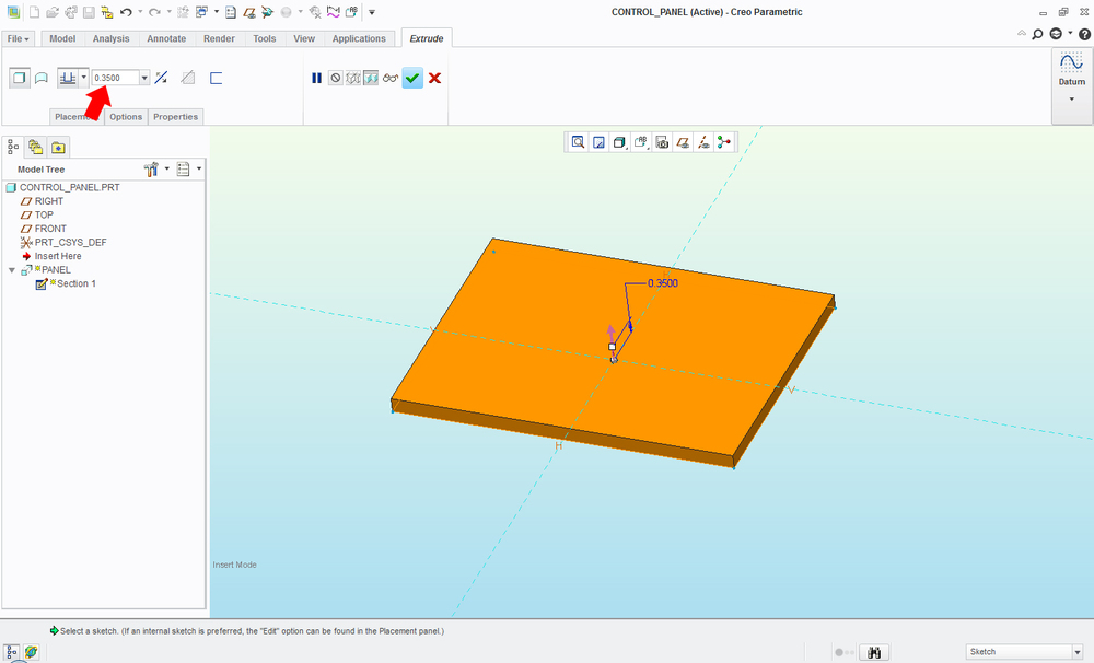
(3) If the computer accepts the shape, it will add depth to it. This is where we move from a 2D drawing to a 3D model. Since I am cutting this out of plywood that is 0.35” thick, I will enter that in the box shown and click OK.
(4) Next, I want to cut a hole for the LCD and a few buttons. I’ll select the surface that I want to create the 2D drawing on. In this case, I’ll choose the top of the panel. Once again, I’ll click the Extrude command for this. Remember: Extrude can add or remove material.
(5) After measuring the size of the LCD screen, I’ll use the Rectangle command to draw the hole where I want it. Now I want to add holes for the buttons. I want the buttons on the right side of the screen, and I want them to be lined up perfectly. I’m going to use what’s called a Centerline for this. You can think of a Centerline as a reference or helper line. In this picture, they are the purple dashed lines. When it comes time to create the 3D model, the computer will ignore these lines, so it doesn’t matter how many you have or where they are placed. Creo will create the center line where I click and it will ‘snap’ to a vertical position, ensuring the buttons are lined up perfectly with the panel.

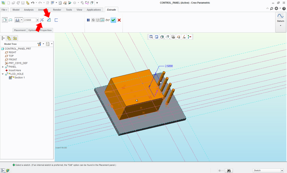
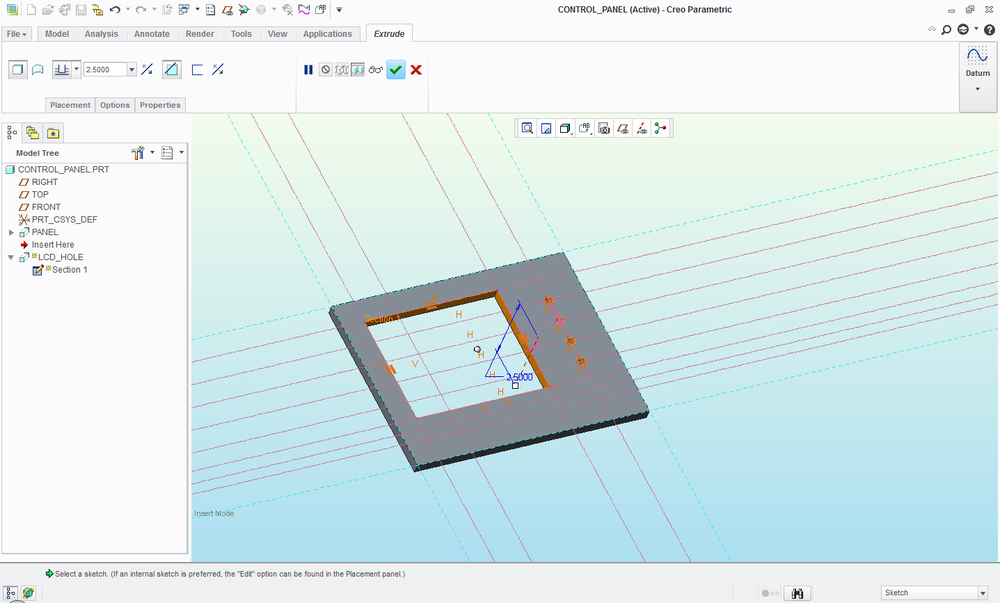
(6) By default, the Extrude command adds material. Since we want to do a cut out, we use the ‘Change Direction’ button on the left to tell the computer to cut away from where we drew the hole and also the ‘Remove Material’ button on the right to tell it to remove material. The result is what we want, a hole for the LCD and holes for buttons. I’ll repeat this process for the other buttons.
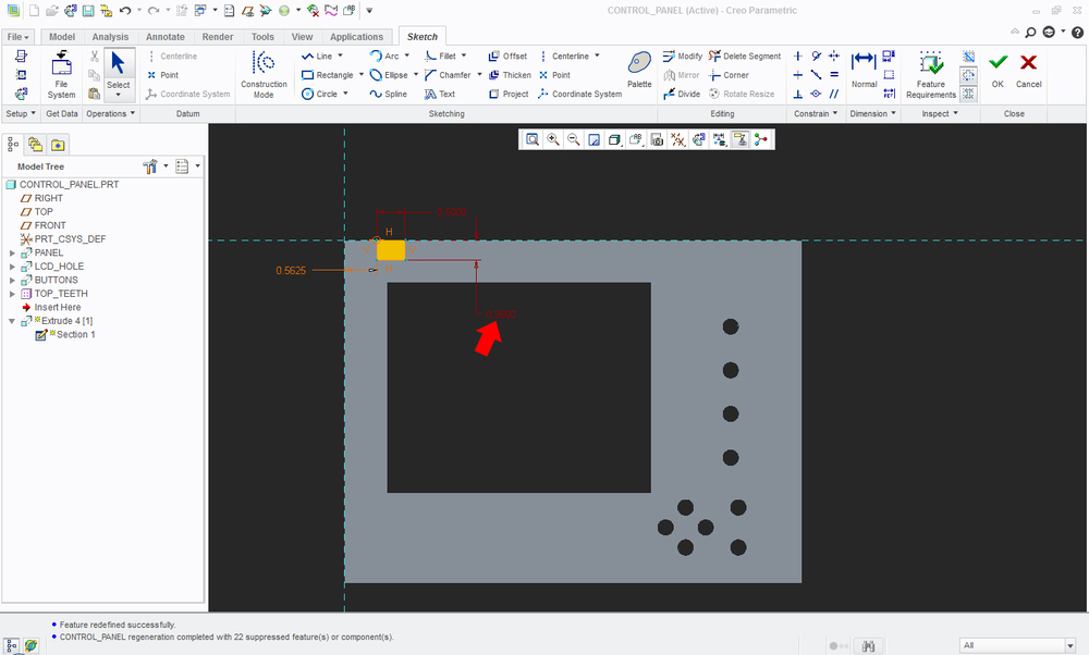
(7) Now it is time to create the ‘teeth’ for the edges. Like before, I select the top surface of the panel and click Extrude. In the Sketcher, I’ll draw a small rectangle that represents one of the teeth I want to cut out. The red color of the dimension indicates that I have locked the dimension. This prevents me or the computer from altering that particular dimension. For now, I am only going to draw one. I’ll show you why in the next step.
(8) Now drawing 7 cutouts would not have taken too much time, but what if we needed to create 1000 teeth around a circular gear? That would take forever. To save time I will use the ‘Pattern’ command. This allows me to duplicate a feature that I had previously drawn. If you look at the red arrows in the picture below, from left to right:
- Direction – tells the computer that you want to pattern in a straight line, as opposed to circular.
- 1 Plane – if you look very carefully, the right side of the panel has an orange line, that is the direction I choose to move.
- 7 – the number of copies I want to make.
- 1.0625 – the spacing between each copy. The black dots represent where the computer will add the feature.
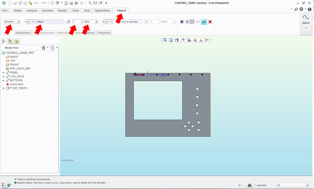
Voilà! We have created the top 8 teeth for our box!
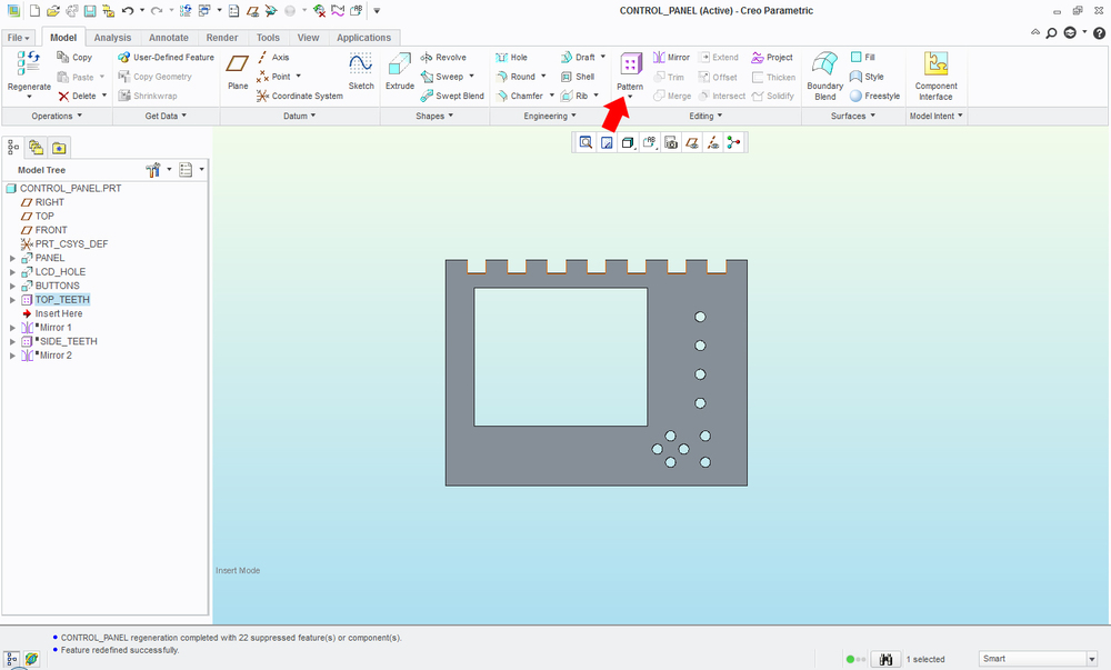
(9) Since the top and bottom of the panel both use the same pattern, we can use the ‘Mirror’ command to do this easily. I’ll turn on the planes again and select the ‘FRONT’ plane because it runs through the center of the panel. Now the computer will take that single tooth that we drew and patterned and copy it to the bottom of the panel.
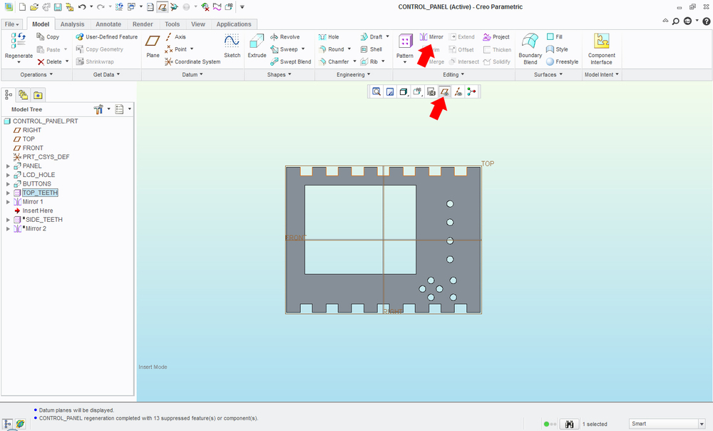
(10) I’ll repeat these last few steps for the teeth on the left and right side of the panel. In the end, we have one part of the box done!