Computer Vision and Projection Mapping in Python
Find the Project-able Area
Now that we have our camera calibration information, the next step in our projector project is determining where our projected image is within the camera view. There are a couple ways to do this. I started off going down the road of projecting another charuco board like we used in the calibration step, but I didn't like the approach because of the extra math to extrapolate the image corners from the marker corners. Instead we'll project a white image, finding the edges and contours in what our camera sees, and pick the largest one with four corners as our projected image. The biggest pitfall here is lighting, so during this step, it might help to dim the lights if you're having trouble.
language:python
#! /usr/bin/env python3
"""
    This program calculates the perspective transform of the projectable area.
    The user should be able to provide appropriate camera calibration information.
"""

import argparse
import json
import time

import cv2
import imutils
import numpy as np

from imutils.video import VideoStream
This beginning part will hopefully start to look familiar:
language:python
def show_full_frame(frame):
    """
    Given a frame, display the image in full screen
    :param frame: image to display full screen
    """
    cv2.namedWindow('Full Screen', cv2.WND_PROP_FULLSCREEN)
    cv2.setWindowProperty('Full Screen', cv2.WND_PROP_FULLSCREEN, cv2.WINDOW_FULLSCREEN)
    cv2.imshow('Full Screen', frame)


language:python
def hide_full_frame(window='Full Screen'):
    """
    Kill a named window, the default is the window named 'Full Screen'
    :param window: Window name if different than default
    """
    cv2.destroyWindow(window)
You'll notice that, while the window name is changed, these are identical to the previous file. Normally I would make a shared module where I would put these helper functions that are re-used, but for the sake of this tutorial, I've left most things in the same file.
language:python
def get_reference_image(img_resolution=(1680, 1050)):
    """
    Build the image we will be searching for.  In this case, we just want a
    large white box (full screen)
    :param img_resolution: this is our screen/projector resolution
    """
    width, height = img_resolution
    img = np.ones((height, width, 1), np.uint8) * 255
    return img
When we go searching for our camera image for our project-able region, we will need some way to define that region. We'll do that by using our projector or monitor to display a bright white image that will be easy to find. Here we have a function that builds that white screen for us. We pass in the projector or screen resolution, and use NumPy to create an array of pixels, all with the value 255. Once we've created the image, we pass it back to the calling function.
language:python
def load_camera_props(props_file=None):
    """
    Load the camera properties from file.  To build this file you need
    to run the aruco_calibration.py file
    :param props_file: Camera property file name
    """
    if props_file is None:
        props_file = 'camera_config.json'
    with open(props_file, 'r') as f:
        data = json.load(f)
    camera_matrix = np.array(data.get('camera_matrix'))
    dist_coeffs = np.array(data.get('dist_coeffs'))
    return camera_matrix, dist_coeffs
You'll remember that in our last section, we calibrated our camera and saved the important information in a JSON file. This function lets us load that file and get the important information from it.
language:python
def undistort_image(image, camera_matrix=None, dist_coeffs=None, prop_file=None):
    """
    Given an image from the camera module, load the camera properties and correct
    for camera distortion
    """
    resolution = image.shape
    if len(resolution) == 3:
        resolution = resolution[:2]
    if camera_matrix is None and dist_coeffs is None:
        camera_matrix, dist_coeffs = load_camera_props(prop_file)
    resolution = resolution[::-1]  # Shape gives us (height, width) so reverse it
    new_camera_matrix, valid_pix_roi = cv2.getOptimalNewCameraMatrix(
        camera_matrix,
        dist_coeffs,
        resolution,
        0
    )
    mapx, mapy = cv2.initUndistortRectifyMap(
        camera_matrix,
        dist_coeffs,
        None,
        new_camera_matrix,
        resolution,
        5
    )
    image = cv2.remap(image, mapx, mapy, cv2.INTER_LINEAR)
    return image
In this function, we are wrapping up our image correction code from our preview during calibration into a more portable form. We start by pulling information about our frame to determine the height and width of the image in pixels. Next we check if we have our camera calibration information. Don't be confused by the function signature, where we can pass in our parameters, or the the file name. This function is used in more than one place, and I decided to make it so you could call the function with the information you had at the time.
Once we have the information we need, we have to reverse the height and width of our resolution. The shape property returns the information in a (height, width, ...) format.
Next we calculate the correction parameters for our image. I'll just point out that this is demo code, and far from ideal. You might notice that every time this function is called, we process the calibration information. That's a lot of extra processing that we end up doing in every camera frame that we want to use. Moving the correction parameters out so they are only calculated once would be a major improvement that would probably improve the overall frame rate of the final project.
Lastly, we correct the image, and return it to the calling function.
language:python
def find_edges(frame):
    """
    Given a frame, find the edges
    :param frame: Camera Image
    :return: Found edges in image
    """
    gray = cv2.cvtColor(frame, cv2.COLOR_BGR2GRAY)
    gray = cv2.bilateralFilter(gray, 11, 17, 17)  # Add some blur
    edged = cv2.Canny(gray, 30, 200)  # Find our edges
    return edged
This function helps us find the edges in our camera image. We start by reducing the number of channels we need to process by converting the image to grayscale. After that, we add some blur into the image to help us get more consistent results. Finally, we compute the edges and return our results.
One thing that I've noticed as I worked through this demo is the amount of "Magic Numbers" that are included in code. "Magic Numbers" are the constants that appear in the code without explanation. For example, in the code above we call the cv2.Canny function with the image frame, but also with the numbers 30 and 200. What are they? Why are they there? Why doesn't the code work without them? These are all questions to avoid in a tutorial, and while I've tried to keep them to a minimum, the libraries we use, like OpenCV, that come from C++, aren't always graceful about their requirements. When it comes to the library functions and methods, I'd recommend browsing the documentation pages like this one, and know that in many cases (like the one above) I've borrowed directly from example code, without fully understanding the importance either.
language:python
def get_region_corners(frame):
    """
    Find the four corners of our projected region and return them in
    the proper order
    :param frame: Camera Image
    :return: Projection region rectangle
    """
    edged = find_edges(frame)
    # findContours is destructive, so send in a copy
    image, contours, hierarchy = cv2.findContours(edged.copy(), cv2.RETR_TREE, cv2.CHAIN_APPROX_SIMPLE)
    # Sort our contours by area, and keep the 10 largest
    contours = sorted(contours, key=cv2.contourArea, reverse=True)[:10]
    screen_contours = None

    for c in contours:
        # Approximate the contour
        peri = cv2.arcLength(c, True)
        approx = cv2.approxPolyDP(c, 0.02 * peri, True)

        # If our contour has four points, we probably found the screen
        if len(approx) == 4:
            screen_contours = approx
            break
    else:
        print('Did not find contour')
    # Uncomment these lines to see the contours on the image
    # cv2.drawContours(frame, [screen_contours], -1, (0, 255, 0), 3)
    # cv2.imshow('Screen', frame)
    # cv2.waitKey(0)
    pts = screen_contours.reshape(4, 2)
    rect = order_corners(pts)
    return rect
This function takes our camera frame, finds the contours within the image, and returns our projection region. We start by calling out to our function that finds the edges within our image. Once we've found our edges, we move on to identifying our contours (or outlines). Here again, you'll find the the OpenCV library has made things easy for us.
Now we need to identify our projection region. I tried many different ways to find our region including feature detection between a reference image and our projected region, and projecting a charuco board to identify the markers, but settled on using contours because they were much simpler and much more reliable. At this point in the code, we have our identified contours, but we need to sort them into some sort of order. We use the Python sorted() function to allow us to do a custom sort in the following way: sorted(what_to_sort, key=how_to_sort, reverse=biggest_first)[:result_limit]. I've added a limit to the number of results we carry around because we only care about the biggest regions in the image (our projection region should be one of the biggest things we can see with four corners).
Once we have our sorted contours, we need to iterate through them, clean up the contour, and find our four-corner winner. We check the number of corners with the len(approx) == 4: command above, and if we've found our box, we save the data and stop searching with our break command.
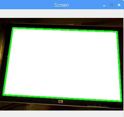
Our last step is to reshape our data into a nicer matrix and put the corner points into the correct order for processing later, before returning it to the calling function.
If all goes well, and you uncomment the lines in the file, you should have something like this:
language:python
def order_corners(pts):
    """
    Given the four points found for our contour, order them into
    Top Left, Top Right, Bottom Right, Bottom Left
    This order is important for perspective transforms
    :param pts: Contour points to be ordered correctly
    """
    rect = np.zeros((4, 2), dtype='float32')

    s = pts.sum(axis=1)
    rect[0] = pts[np.argmin(s)]
    rect[2] = pts[np.argmax(s)]

    diff = np.diff(pts, axis=1)
    rect[1] = pts[np.argmin(diff)]
    rect[3] = pts[np.argmax(diff)]
    return rect
This function uses the sum and diff along with the min and max to figure out which corner goes where, matching the order that we'll need to use later to transform our space.
language:python
def get_destination_array(rect):
    """
    Given a rectangle return the destination array
    :param rect: array of points  in [top left, top right, bottom right, bottom left] format
    """
    (tl, tr, br, bl) = rect  # Unpack the values
    # Compute the new image width
    width_a = np.sqrt(((br[0] - bl[0]) ** 2) + ((br[1] - bl[1]) ** 2))
    width_b = np.sqrt(((tr[0] - tl[0]) ** 2) + ((tr[1] - tl[1]) ** 2))

    # Compute the new image height
    height_a = np.sqrt(((tr[0] - br[0]) ** 2) + ((tr[1] - br[1]) ** 2))
    height_b = np.sqrt(((tl[0] - bl[0]) ** 2) + ((tl[1] - bl[1]) ** 2))

    # Our new image width and height will be the largest of each
    max_width = max(int(width_a), int(width_b))
    max_height = max(int(height_a), int(height_b))

    # Create our destination array to map to top-down view
    dst = np.array([
        [0, 0],  # Origin of the image, Top left
        [max_width - 1, 0],  # Top right point
        [max_width - 1, max_height - 1],  # Bottom right point
        [0, max_height - 1],  # Bottom left point
        ], dtype='float32'))
    return dst, max_width, max_height
This function builds the matrix we will need to transform from our skewed view of the projection region into a perspective-corrected, top-down view that we need to accurately manipulate our data.
We start by computing the distance between our x coordinates on the top and bottom of the image. Next, we do the same with our y coordinates on the left and right side of the image. Once these calculations are finished, we save the max width and height to use in our matrix creation.
To create our matrix, we provide the computed values of our four corners based on our max width and height.
Finally we return the important data back to the calling function.
language:python
def get_perspective_transform(stream, screen_resolution, prop_file):
    """
    Determine the perspective transform for the current physical layout
    return the perspective transform, max_width, and max_height for the
    projected region
    :param stream: Video stream from our camera
    :param screen_resolution: Resolution of projector or screen
    :param prop_file: camera property file
    """
    reference_image = get_reference_image(screen_resolution)

    # Display the reference image
    show_full_frame(reference_image)
    # Delay execution a quarter of a second to make sure the image is displayed
    # Don't use time.sleep() here, we want the IO loop to run.  Sleep doesn't do that
    cv2.waitKey(250)

    # Grab a photo of the frame
    frame = stream.read()
    # We're going to work with a smaller image, so we need to save the scale
    ratio = frame.shape[0] / 300.0

    # Undistort the camera image
    frame = undistort_image(frame, prop_file=prop_file)
    orig = frame.copy()
    # Resize our image smaller, this will make things a lot faster
    frame = imutils.resize(frame, height=300)

    rect = get_region_corners(frame)
    rect *= ratio  # We shrank the image, so now we have to scale our points up

    dst, max_width, max_height = get_destination_array(rect)

    # Remove the reference image from the display
    hide_full_frame()

    m = cv2.getPerspectiveTransform(rect, dst)

    # Uncomment the lines below to see the transformed image
    # wrap = cv2.warpPerspective(orig, m, (max_width, max_height))

    # cv2.imshow('all better', wrap)
    # cv2.waitKey(0)
    return m, max_width, max_height
Here's where we start to put the pieces together. Take a look at the in-line comments here, as they'll probably be more helpful than a summary paragraph at the end.
We start by building our solid white image to the resolution of our screen or projector. Once we have that, we display it for our camera to see. We delay our image capture a quarter-second to make sure the image has time to get up on the display, then snap a frame.
Working with full size images is slow, so we compute and save a resize ratio, then make our frame smaller. Once we've computed the corners of our projection region, we use our saved ratio to make our found region match the locations in our original image.
Using our new corner data, we call our function that computes the destination array for our perspective transform. We stop displaying our reference (white) image, and then use the returned data to calculate our perspective transform.
You'll see some lines here that are commented out. If you'd like to see the corrected image, uncomment these lines. This can be helpful to visualize what is happening at each step.
Finally we return our perspective transform and the max width and height.
language:python
def parse_args():
    """
    A command line argument parser
    :return:
    """
    ap = argparse.ArgumentParser()
    # Camera frame resolution
    ap.add_argument('-cw', '--camera_width', type=int, default=960,
                    help='Camera image width')
    ap.add_argument('-ch', '--camera_height', type=int, default=720,
                    help='Camera image height')
    # camera property file
    ap.add_argument('-f', '--camera_props', default='camera_config.json',
                    help='Camera property file')
    # Screen resolution
    ap.add_argument('-sw', '--screen_width', type=int, default=1680,
                    help='Projector or screen width')
    ap.add_argument('-sh', '--screen_height', type=int, default=1050,
                    help='Projector or screen height')
    return vars(ap.parse_args())
This next function is just a way to use Python's argparse to build a command line parser. This allows us to feed in these commands and override settings without the need for changing the code. You might notice that I have flags for camera width and camera height. Parsing values with spaces and such is tricky, so instead of passing in a tuple (think (width, height)) I just set each individually.
language:python
>fbset -s
If you're unsure what your screen resolution is, this bash command makes it easy to find.
language:python
if __name__ == '__main__':
    args = parse_args()
    # Camera frame resolution
    resolution = (args.get('camera_width'), args.get('camera_height'))

    stream = VideoStream(usePiCamera=True, resolution=resolution).start()

    time.sleep(2)  # Let the camera warm up

    screen_res = (args.get('screen_width'), args.get('screen_height'))
    get_perspective_transform(stream, screen_res, args.get('camera_props'))
    stream.stop()
    cv2.destroyAllWindows()
Here is the main control of our program. You can see the main program flow here. We start by gathering our arguments and starting our video stream. After that, we call our function get_perspective_transform and pass it the information it needs. Once we have our information, we clean up by stopping our camera stream and cleaning up any windows that might be open.