Building an Autonomous Vehicle: The Batmobile
Control Electronics - Locomotion
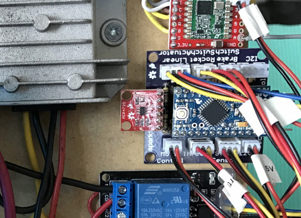
Note the polarized connectors and prodigious labeling! You DO NOT want to be guessing what gets plugged into where at 11 p.m. before race day. The Locomotion Controller code is available here, and the PCB layout here.
Because we eventually wanted this beast to be autonomous, we needed to put a controller in the middle between the throttle and the motor controller. We used an Arduino Pro Mini that did a huge variety of sensing and control:
- Read the throttle
- Output analog voltage to the motor controller
- Read the brake switch
- Read the steering position
- Controlled the linear steering actuator
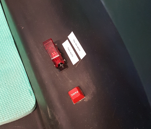
- Read the human/robot control switch
- Received and responded to control commands over I2C
The controller would monitor the rocket switch and brake switch. If a human ever pressed the brakes or turned off the rocket switch, the controller would go into safety shutdown and ignore any commands from the brain.
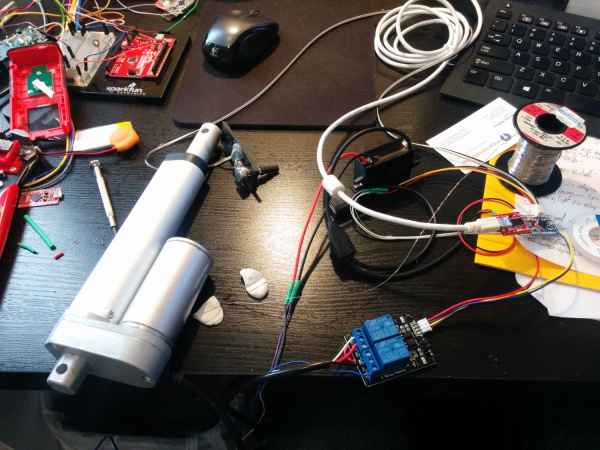
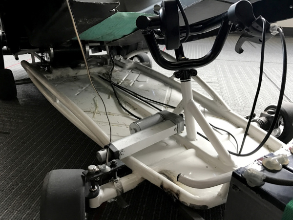
Steering was controlled using a 12V linear actuator over-voltaged to 24V for extra speed. Two relays controlled the forward/backward motion.
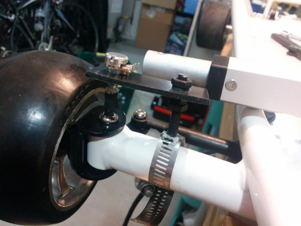
Steering position was obtained by cutting a hex wrench to about 1” and inserting that wrench into the bolt that rotates with the wheel. The wrench was then connected to a 10k trimpot using adhesive-lined heat shrink -- this trick is known as the "poor man’s coupler:" a 3-wire ribbon connected the trimpot back to the locomotion controller. It worked well, but we had to keep the analog signal wire away from the power bus; otherwise, bad noise got into the ADC readings.
For future vehicles, we're going to change this setup. It worked well enough, but once the bolt connected the actuator to the steering, you couldn’t drive the car; only the computer could. So rather than driving the car to the start line, we had to carry this 75lb beast. So painful. In the future, we plan to find a back-drivable actuator or maybe drive-by-wire.
