Blynk Board Arduino Development Guide
 jimblom
Load an Example Program
- Blynk by Volodymyr Shymanskyy v0.6.1
- NeoPixel by Adafruit v1.2.1
With the Blynk auth token at hand and the project set up, you're armed with all of the information you'll need to get your board Blynking again.
Configure the Code
Copy and paste this code into your Arduino IDE, but don't upload it yet!
language:c
#define BLYNK_PRINT Serial    // Comment this out to disable prints and save space
#include <ESP8266WiFi.h>
#include <BlynkSimpleEsp8266.h>  // http://librarymanager/All#blynk
#include <Adafruit_NeoPixel.h>   // http://librarymanager/All#neopixel

////////////////////
// Blynk Settings //
////////////////////
char BlynkAuth[] = "Your_Auth_Token";
char WiFiNetwork[] = "Your_WiFi_Network";
char WiFiPassword[] = "Your_WiFi_Password";

///////////////////////
// Hardware Settings //
///////////////////////
#define WS2812_PIN 4 // Pin connected to WS2812 LED
#define BUTTON_PIN 0
#define LED_PIN    5
Adafruit_NeoPixel rgb = Adafruit_NeoPixel(1, WS2812_PIN, NEO_GRB + NEO_KHZ800);

BLYNK_WRITE(V0) // Handle RGB from the zeRGBa
{
  if (param.getLength() < 5)
    return;

  byte red = param[0].asInt();
  byte green = param[1].asInt();
  byte blue = param[2].asInt();

  uint32_t rgbColor = rgb.Color(red, green, blue);
  rgb.setPixelColor(0, rgbColor);
  rgb.show();
}

void setup()
{
  // Initialize hardware
  Serial.begin(9600); // Serial
  rgb.begin(); // RGB LED
  pinMode(BUTTON_PIN, INPUT); // Button input
  pinMode(LED_PIN, OUTPUT); // LED output

  // Initialize Blynk
  Blynk.begin(BlynkAuth, WiFiNetwork, WiFiPassword);
}

void loop()
{
  // Execute Blynk.run() as often as possible during the loop
  Blynk.run();
}
Before uploading the code, you'll need to adjust three variables towards the top of the sketch:
- Paste your Blynk auth token over
Your_Auth_Token, setting theBlynkAuthvariable. - Paste your WiFi network name over
Your_WiFi_Network, setting theWiFiNetworkvariable. - Paste your WiFi password over
Your_WiFi_Password, setting theWiFiPasswordvariable- If the network is open, leave the string empty (
"").
- If the network is open, leave the string empty (
Upload the Code
Before uploading, you'll need to configure the serial port -- the "COM#" or "/dev/tty.usbserial-########" number you discovered way back at the FTDI driver-installation phase. Knowing that, navigate to Tools > Port, and select your port number.
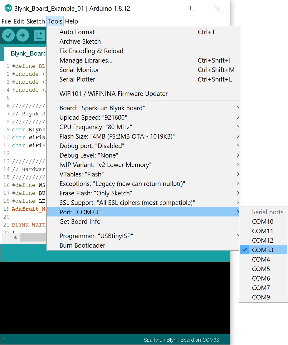
We also suggest increasing the upload rate to 921600. You'll find that setting under the Tools > Upload Speed option.
This is the moment of truth! Once the code has been configured, hit the Upload button (the right-pointing arrow).
Your computer may take a minute-or-so to compile the code and send it over to the Blynk board. Arduino should inform you if the upload was successful or not. If not -- double check the board and port settings, and give it another try. Sometimes that's all it takes.
Check the Serial Monitor
If the code successfully uploads, open the serial monitor -- the magnifying glass icon, in the upper right portion of the Arduino IDE.
This window will pass some handy debug information. It'll tell you if the Blynk Board successfully connected to your WiFi network and the Blynk server.
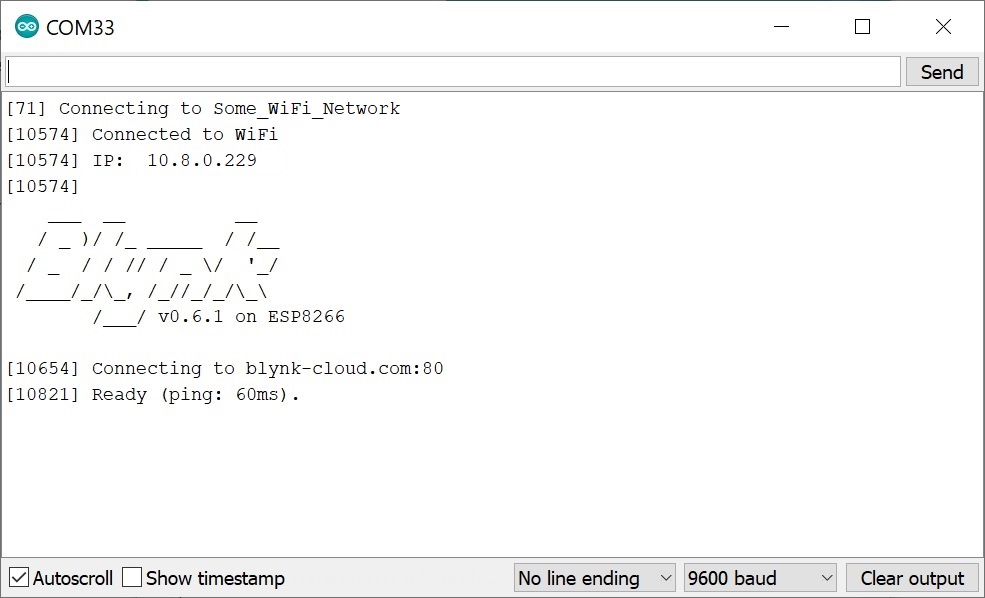
If you see a "Ready" message -- you should be good to Blynk! Do some zeRGBa'ing, press some buttons, and adjust some analog inputs! You're well on your way to making your own Blynk projects.