$19.95
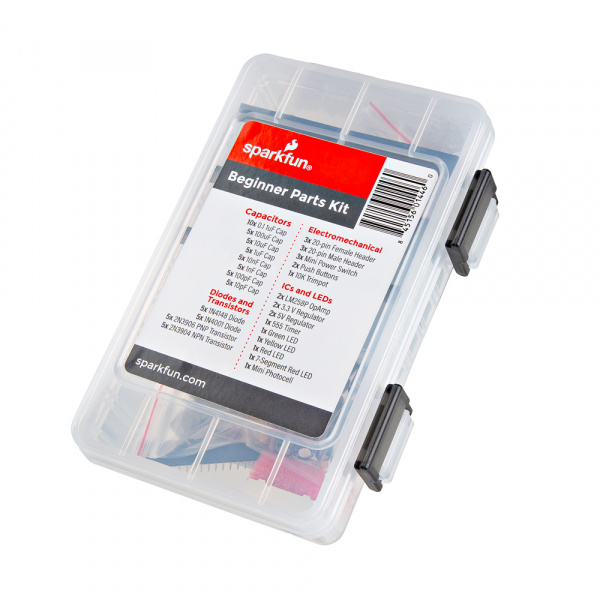
As you dig deeper into the electronics hobby, you'll probably find your personal space infiltrated by a recurring theme of electronics components. With the Beginner Parts Kit we've tried to create a delightful mish-mash of electronics components that us electrical engineers have grown to love and/or hate through the years. It's filled with capacitors, LEDs, transistors, integrated circuits, and the like that we've found to be the most useful components around. And they all come in a pretty kickin' box too! Whether you're beginning an electronics collection, or just refilling, the Beginner's Parts Kit will have a lot of what you need.
In this tutorial, we'll provide a quick rundown of each part in the kit, to help reinforce your understanding of the component. For some parts, we'll include an example application, in case you're in need of a circuit to plug your new toys into.
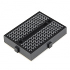
To follow along with this tutorial, you will need the following materials at a minimum to get started. You may not need everything though depending on what you have. Add it to your cart, read through the guide, and adjust the cart as necessary. The breadboard size will depend on the size of your circuit. For building each individual circuit, the smaller breadboard will suffice. As you get start combining circuits, you will need a larger breadboard.
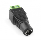
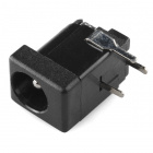
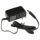
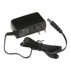
In addition to those components, you need an actual power source that delivers a voltage that's 1-2V higher than your desired output. If I have a wall outlet available, I always like using "wall-warts" as my power supply; of those 9V or 12V are good options. The output of the wall-wart can be plugged into a barrel jack connector, which can, in turn, be wired to our circuit.
If you aren’t familiar with the following concepts, we recommend checking out these tutorials before continuing.
You will find the following parts in the kit.
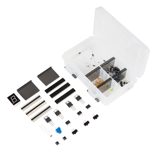
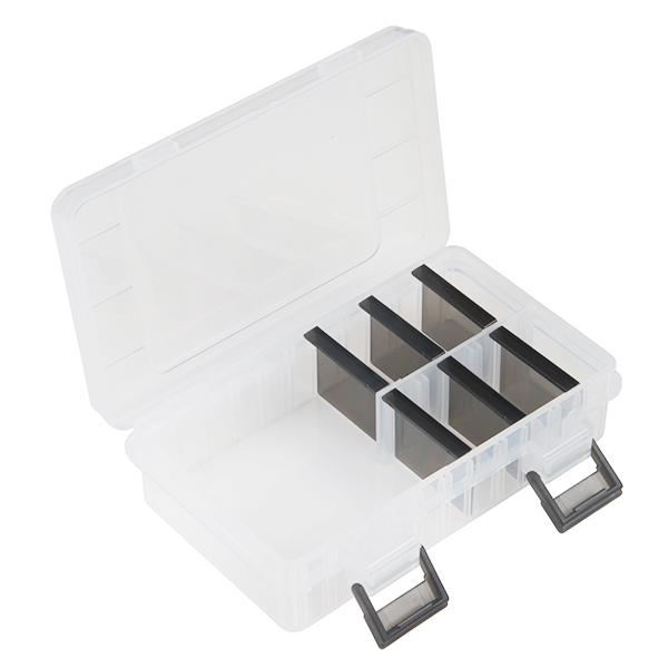
Though it's lacking in real electrical characteristics, the Parts Box remains one of the coolest parts of the Parts Kit. When the components have grown out of the box's comfortable confines, into a circuit of their own, the Parts Box will remain to someday host a new family of components. Previous SparkFun part boxes consisted of two latching lids with different compartments. Our latest part box contains individual, adjustable dividers.
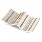
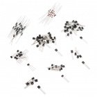
Never really going to have a starring role in a circuit, capacitors are nevertheless at the foundation of most designs. These caps are most commonly used for circuit decoupling, where they're placed in parallel with a DC voltage supply to suppress noise. They've got loads of other uses as well, such as energy storage and timing circuit tuning (see the 555 timer below).
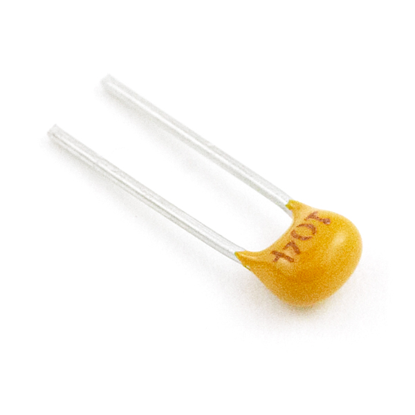
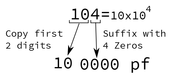
Each of these caps can be distinguished by the tiny print on their body. See the table below to match up each cap with its value, you'll probably notice a pattern:
| Cap Value | Cap Marking |
|---|---|
| 10pF | 100 |
| 100pF | 101 |
| 1nF | 102 |
| 10nF | 103 |
| 0.1uF | 104 |
| 1uF | 105 |
A not-too-distant cousin of the ceramic capacitor, these electrolytic caps have one very distinct trait: they are polarized, meaning they have both a positive and a negative leg.
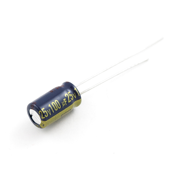
The negative leg is marked by both a "– " looking sign on the body of the cap (gold on the 100uF and white on the 10uF), and a shorter leg. Take care to ensure that the voltage on the long, positive lead is higher than that on the negative lead. If you do happen to hook the cap up backwards, catastrophic failure is imminent, usually in the form of the cap making a fun 'pop' noise, and sort of puffing out. Sounds fun, I know, but you've only got five of each, so you may want to keep them in working order.
For more information, check out our tutorial about capacitors.
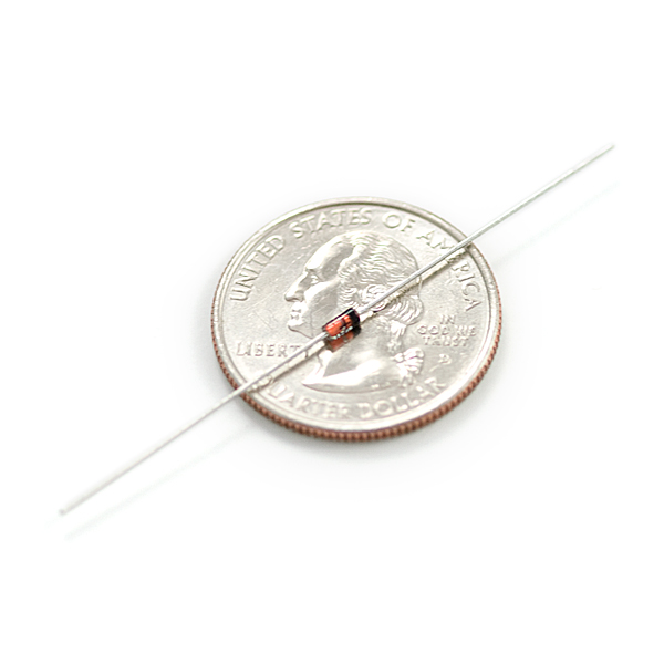
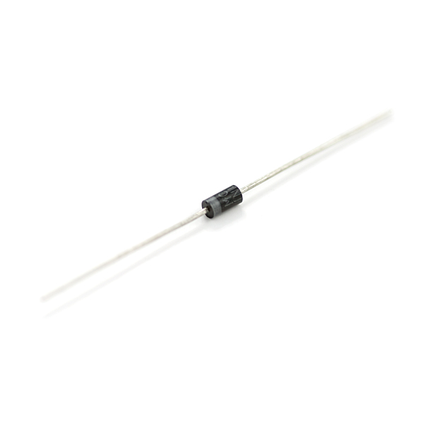
Diodes are used to ensure that current only flows in one direction, this comes at the cost of a small forward drop across them. There are two varieties of diodes in this kit: the 1N4148 small-signal diode, and the 1N4001 rectifying diode. The 1N4148 is the neat looking orange-and-black diode, where the black line marks the negative (cathode) side. The 1N4001 is the black and gray diode, and the gray line marks its cathode.
Both diodes share the usual diode characteristics, however they differ in their electrical ratings. The 1N4001 has a much higher forward current rating, 1000mA, compared to the 1N4148's 200mA rating, but it also has a slightly higher forward voltage rating. Because of its relatively high-current rating, the 1N4001 usually takes a role in power conversion circuits, like DC-DC converters, and AC-DC rectifiers. The small-signal 1N4148's are better used in low-current applications, like logic circuits.
For a much deeper read on diodes, check out our diode tutorial.
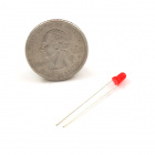
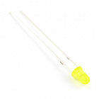
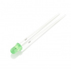
No project is complete without a blinking LED. That's a fact! The parts kit includes one of each green, yellow, and red 3mm LEDs.
LEDs have two terminals, an anode, the positive side, and a cathode, the negative side. The two terminals can be distinguished in two ways. If you look at the base of the diode, you'll notice it's not exactly round, there's a flat edge that signifies the cathode. I'm terrible at seeing the flat edge though, so I usually look for the shorter of the two legs, which also indicates the cathode.
There are two aspects to illuminating an LED: the LED requires a specific positive voltage, and it also needs just enough, but not too much, forward current. These ratings for all three LEDs are in the table below.
| LED Color | Suggested Forward Current | Max. Forward Current | Typical Forward Voltage |
|---|---|---|---|
| Green | 16-18mA | 20mA | 2.0V-2.4V |
| Yellow | 16-18mA | 20mA | 2.0V-2.4V |
| Red | 16-18mA | 20mA | 1.8V-2.2V |
For a great discussion on LEDs, check out our LED tutorial.
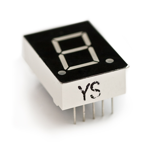
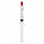
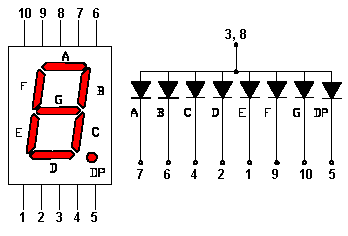
Taking a starring role in the Parts Kit is this rectangular component, which houses eight LEDs total.
Seven LEDs comprise what we call a 7-Segment display, and can be turned on or off to create any number or near-representations of many other characters. An eighth LED controls a decimal point to the bottom right of the digit. You've no doubt seen 7-Segment LEDs in other big-time roles, like your alarm clock, radio, microwave, and tons of other devices that need to show a numerical value.

The 7-Seg LED has 10-pins, five on each the top and bottom of the display. All LEDs share a common anode, pins 3 and 8, while the rest of the pins are the individual cathodes of each LED.
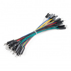
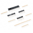
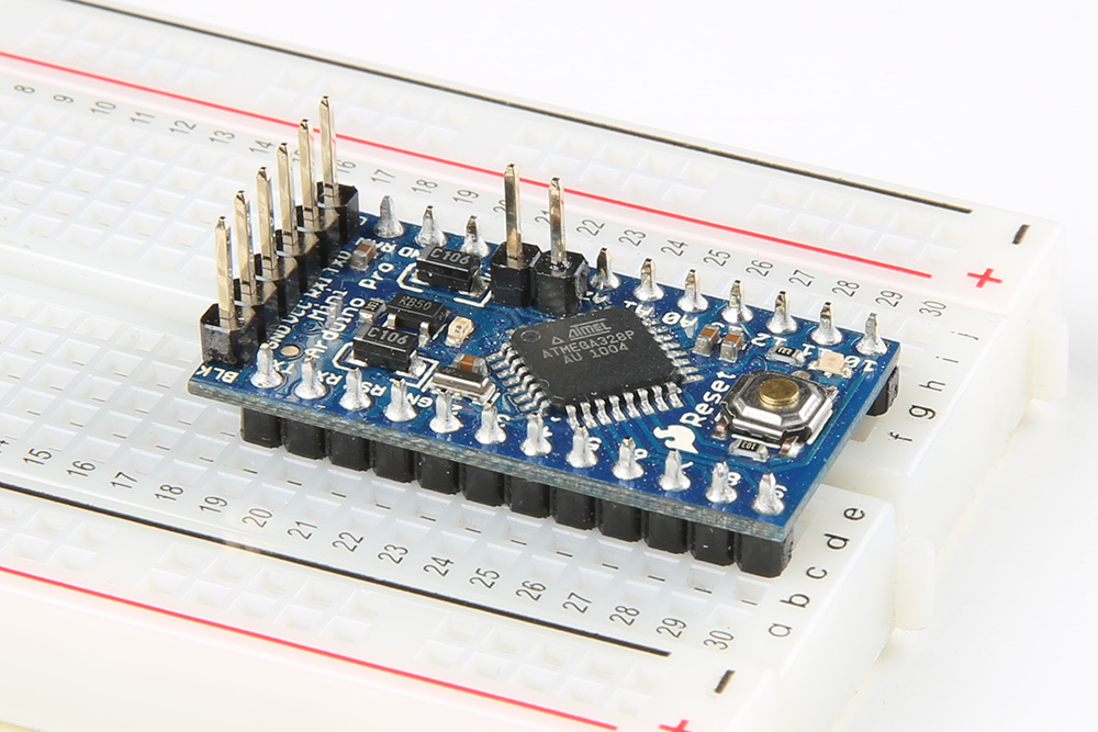
This happy couple isn't all that exciting, but they're an important component nevertheless. If you ever find yourself with a SparkFun breakout board, you may need to solder in one of these headers to form a solid, electrical connection between the board and another component. The male headers are useful if you want to plug the breakout board into a breadboard, while the female headers are useful for plugging wires into. You can also use them to help solder pins to boards.
 |
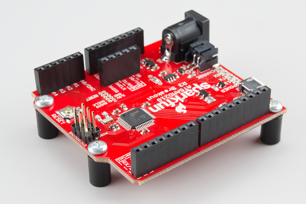 |
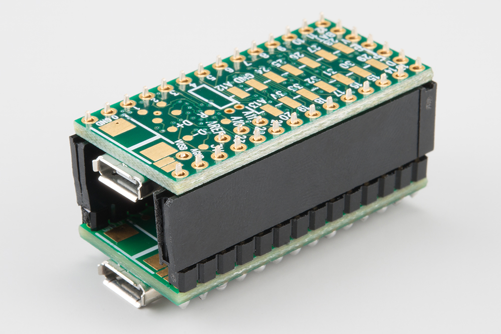 |
| Male Headers Soldered on Arduino Pro Mini | Female Headers Soldered to SAMD21 | Teensy's Stacked to Help with Soldering Soldering |
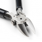
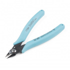
These headers come in sets of 20 pins, and can be broken into smaller sets with a set of clippers.
At the heart of any great project is user input, exactly what these switches and buttons are built for.
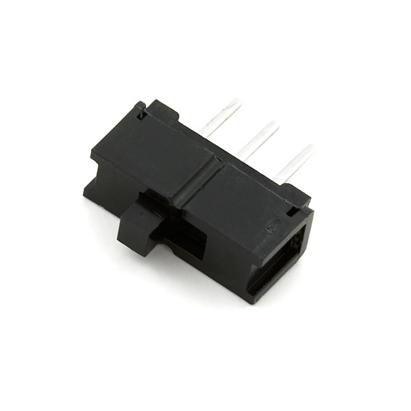
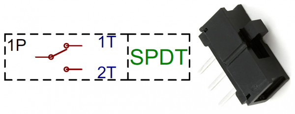
The Mini Power Switch often lands roles as on/off control, but it can control many other functions. This single-pole/double-throw (SPDT) switch has three terminals, one of the two outer-terminals will be connected to the middle one, whichever one it is will depend on the direction the switch is flipped in. It's all pretty intuitive.
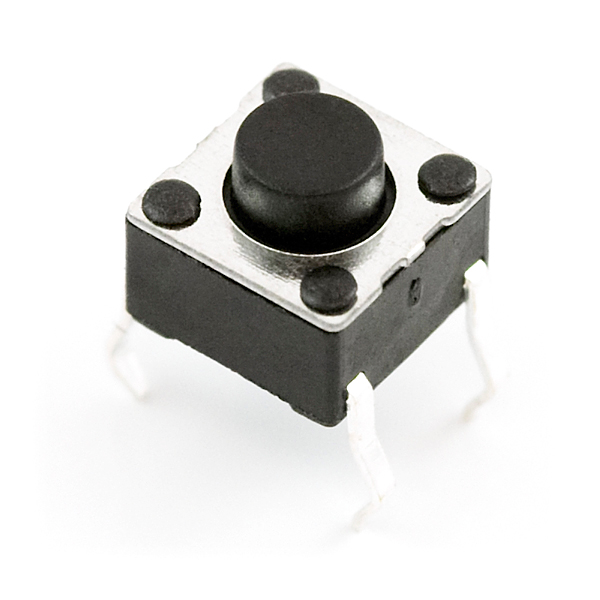
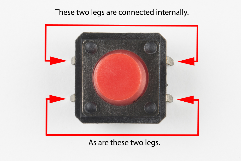
The Push Buttons have two terminals; of the four leads two on each side are shorted together. When the small black button is depressed, the terminals are shorted together, otherwise the button acts as an open circuit. Where the switch is used as an on/off control, the button is used for more momentary control, like a quick reset. Here's an annotated top view of a 12mm colored button annotated.
For more information, check out our switch basics.
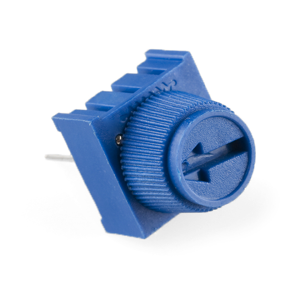
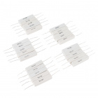
The only real resistive component in the Parts Kit is the 10kΩ potentiometer. Like the buttons, a potentiometer can be used as a form of input; for instance if you've ever set a speaker's volume to 11, you were probably rotating the knob of a potentiometer.
The potentiometer has three terminals. The resistance across the two outer terminals will always be 10kΩ. Meanwhile, as the knob is rotated, the resistance between the center terminal, called the wiper, and either of the two outer terminals will vary from 0 to 10kΩ.
For more information about this variable resistor, check out our resistors tutorial.
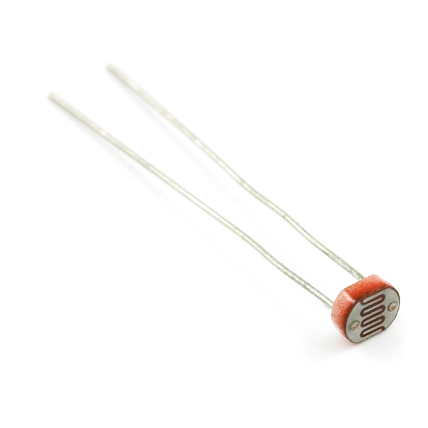
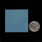
This component also goes by the name of photoresistor. It's a really neat device that functions almost like a potentiometer, except that the wiper's been replaced with a light-sensitive semiconductor material. The resistance between the two terminals of the photocell are dependent upon the amount of light that's incident upon the top of the cell. In complete darkness the resistance will be around 1MΩ while in bright light the resistance may be as low as 1kΩ. Photocells obviously make great light sensors, if you want a device to only turn on when you've flipped a light switch, the photocell would be a perfect player in your project.
For more information, check out the photocell hookup guide.
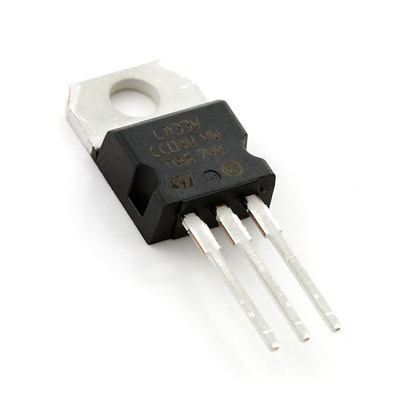
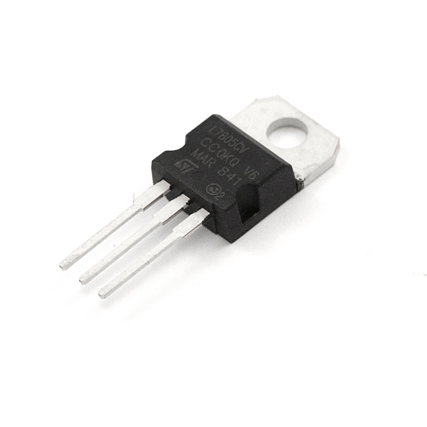
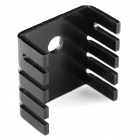
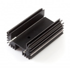
Working behind the scenes in most circuits are the voltage regulators, ever-toiling to convert those unfriendly, unstable, high-voltage signals to something that keeps everything in the rest of the circuit happy.
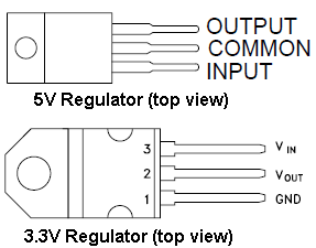
The voltage regulators included in the Parts Kit are of the linear variety, they can be used to drop a large voltage down to either 5V or 3.3V. In exchange for this energy transfer, they'll produce anywhere from a slight warmth to searing, painful heat on the bottom, metal tab.
Each regulator has just three pins: an input voltage, an output voltage, and a common ground. The pinouts of the two regulators are annoyingly not the same, so take note of the picture below.
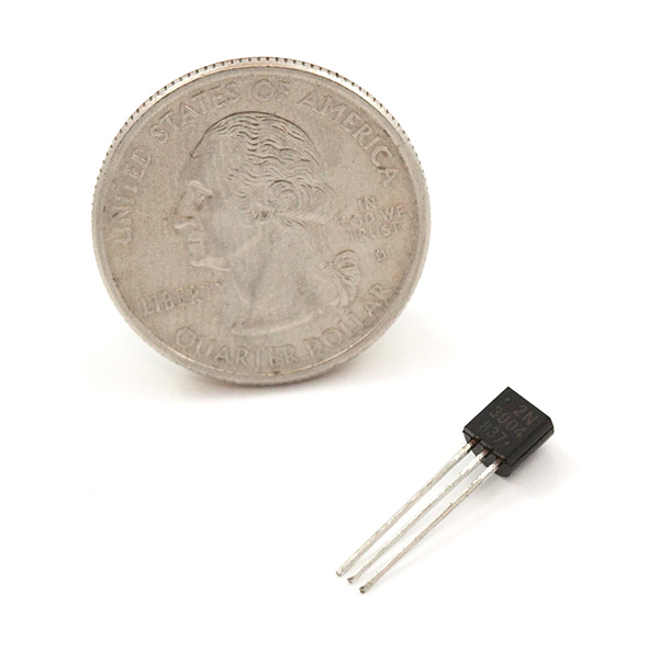
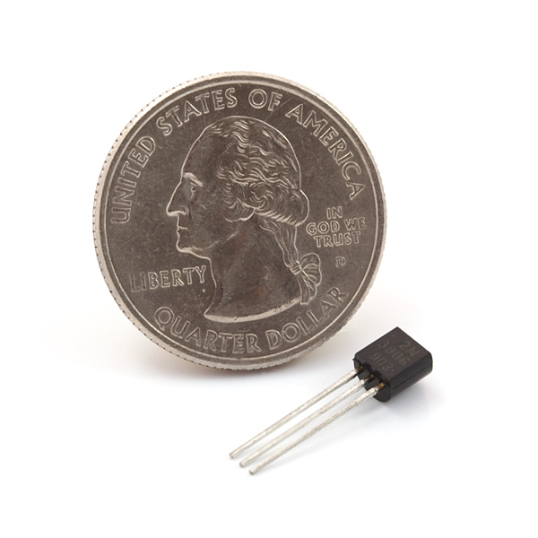
A distant relative of the diode, the transistors are also a semi-conductor device.
Though you probably haven't seen them, transistors have been in just about every electrical device you've ever used. The transistors included represent both types of bipolar junction transistors (BJTs), NPN and PNP, and are some of the most common transistors around.
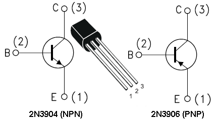
Transistors can be thought of as electronic switches. They have three terminals: a collector, an emitter, and a base. The base acts as the control of the switch; whether it's pulled high or low controls whether current can flow from the collector to the emitter. For the NPN diode, current will flow from C to E if the base is pulled high (relative to the emitter), conversely, on the PNP transistor, the base must be pulled low relative to the emitter for current to flow from C to E.
For a much deeper read on diodes, check out our diode tutorial.
Operational amplifiers...depending on how much you love analog circuit design, these integrated circuits either conjure painful memories of ideal amplifier theory, or delightful recollections of amplifier circuit design. Fortunately, there's a lot of information out there to help you get exactly what you want out of an op-amp. Op-amps are a specifically differential voltage amplifiers, they take two voltage inputs and amplify the difference to anywhere from 10s to 1000s of times larger. They have zillions of applications; depending on the components around them they can be used to compare, invert, add, integrate, or perform all sorts of other functions on signals.
The AS358 and LM358 are good examples of a really standard op-amp. One of the 358 op-amps will be included in the kit.
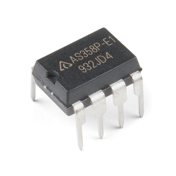
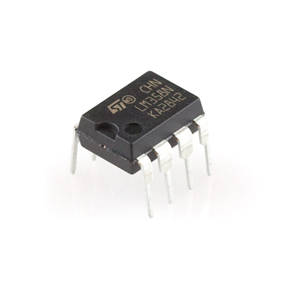
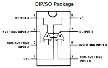
It's dual channel, meaning it's actually got two op-amps inside it. Each amp has an inverting and non-inverting input, as well as a single output. And both amps share a single voltage supply.
For more information about operational amplifiers, check out our tutorial.
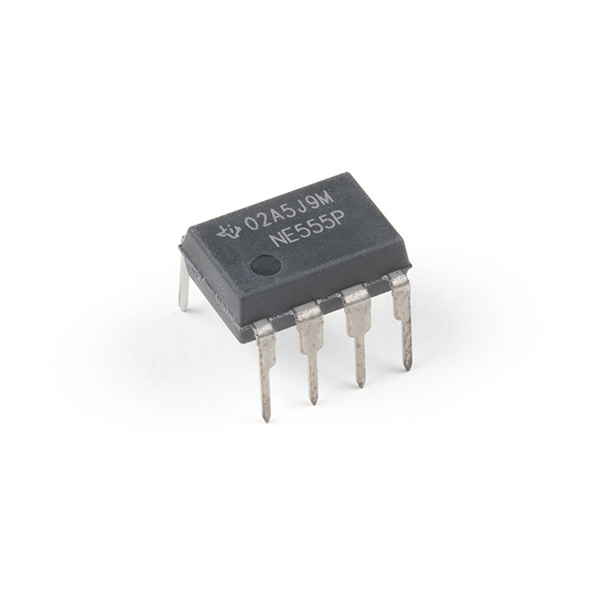
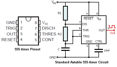
Closing up the cast of components is this staple of timing circuits.
It's a component whose use is so open-ended that contests are held to see who can conceive of the most useful, complex, and/or artistic use of the thing. With the 555 at the heart of a circuit, and a handful of choice resistors and capacitors, you can create a variety of waveforms that oscillate at frequencies from thousandths to hundreds of thousands of a Hz.
Looking for more examples with the 555? Check out the link below for 555 timer circuits.
Below we'll tackle a few common circuits that use components from the Parts Kit. Hopefully, they'll spring ideas for new projects. Unfortunately, the parts kit doesn't have quite everything you'll need to complete these quick circuits, but I'll link any additional parts you'll need. A common theme of all of these projects is they're breadboard based, if you're looking for an addition to your parts catalog, and you don't already have one, a breadboard is a great place to start. You may also want to add a resistor kit, power supply, and adapter to your collection as well.
We can use the included voltage regulators, 1N4001 diode, and capacitors to create a regulated power supply.
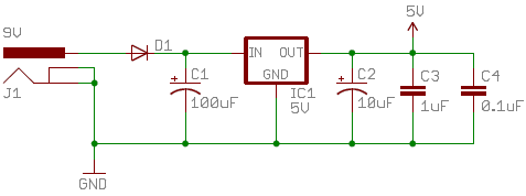
From the barrel jack connector, we first run power into the 1N4001 diode. Because the diode conducts current only in the positive direction, this adds reverse power protection to the circuit. If someone were crazy enough to connect the barrel jack backwards, the diode would protect the C1 capacitor and the regulator from being subjected to -9V (remember our talk about blowing up electrolytics?).
You'll notice caps thrown about everywhere around the circuit; these are all decoupling caps, used to limit the noise in the power supply. When adding decoupling caps, it's always beneficial to add a range of values, and even different types of capacitors. Depending on the desired output voltage, you can use either the 3.3V or 5V regulator. That's it, you've got a nice, happy, regulated supply; the first and most important step in project design. If you want to take this design a step further, you could add a resistor and an LED, to act as a power indicator. To toggle power, try adding the switch between the diode and voltage regulator.
Sometimes the simplest circuits can be the most enthralling, awesome things ever. That's the case with this circuit, all you need is a power supply, a photoresistor, and an LED.
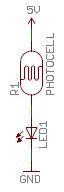
The photoresistor limits the current that flows through the LED, thus controlling the brightness. See if you can turn the LED completely off; I sure couldn't. Then see how bright you can get the LED, as it plays the part of Icarus soaring ever-closer to it's light source.
If you're like me, that circuit's a little counter-intuitive. The LED should turn on when it's dark, off when it's light; an automatic nightlight. The addition of a transistor, and a couple resistors solves that problem:
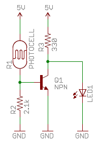
In this circuit the transistor acts as an inverter. If the resistance of the photocell is low, meaning it's bright out, the transistor is on, and the LED is pulled towards ground. If the photocell's resistance is high, and it's dark out, the transistor turns off and the LED is turned on. That's the magic of transistors! You may need to play with the R2 resistor to adjust the sensitivity of your nightlight.
There's not a whole lot you can say with one character, but you could get a little creative and use it with a switch, to display multiple characters on a single display. Say you have a special affinity for the number 13, you could use the Mini Power Switch in addition to a 330Ω resistor and the Red 7-Segment Display to (sort-of) display it.
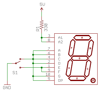
The resistor is added to limit the current going into all of the segments; you don't want to blow up your pretty red LEDs. Now flip the switch really quickly and visualize that 13! Maybe you could add a potentiometer, allowing you to dim the LED.
Continuing on the premise that blinky things rule, let's use the 555 timer to control an LED that keeps a beat. Again you'll need a few resistors, in addition to a 555, 10uF capacitor, 10nF capacitor, and an LED.
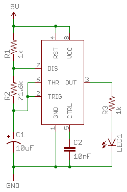
Blinkies! The 555 timer is running in astable mode, which means it continuously outputs square waves at a near 50% duty cycle. You can adjust the value of R2 to speed up, or slow down the blinky. Try replacing R2 with a potentiometer.
Hopefully these examples provide you with a good idea of what kind of magic you've got in that parts box. Now it's time to create something amazing; and when you do, let us know about it!
Looking for other great essentials for your parts box or tools? Check out some of these other great kits and books!

Need some inspiration to start prototyping? Try looking at the following tutorials for ideas!
Or check out some of these blog posts for ideas:
Have a suggestion for how we can improve this guide? Steps missed? Instructions unclear? Please let us know. You can leave a comment below or contact us through our support team. Also, let us know if this is the most awesome assembly guide you've ever encountered and we'll stop trying to improve it.
learn.sparkfun.com | CC BY-SA 3.0 | SparkFun Electronics | Niwot, Colorado