Introduction to Operational Amplifiers with LTSpice
 LightningHawk
Introduction
If you haven't already been through the Getting Started with LTSpice guide, you should definitely wait as an update to the audio quality is desperately needed. For those of you who watched it and finished it - bless you. I'd thought I'd kill two birds with one stone here and continue the LTSpice tutorial with an introduction to operational amplifiers -- or op amp for short. We will be covering just the basics here - what are op amps, some common configurations, and a couple examples - and we'll end with a nice, simple project to hopefully get you inspired to work with analog circuits a bit more.
To get started, download the schematics, symbols and simulations by clicking the button below.
Introduction to Operational Amplifiers
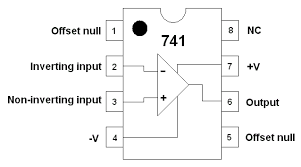
An op amp is a voltage amplifying device. With the help of some external components, an op amp, which is an active circuit element, can perform mathematical operations such as addition, subtraction, multiplication, division, differentiation and integration. If we look at a general op amp package (innards to come in a later tutorial) such as the ubiquitous 741, we'll notice a standard 8-pin DIP (dual in-line package):
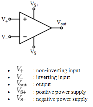
We are mainly concerned with five of the pins. The circuit symbol for an op amp is a triangle with five pins shown below.
An op amp has a wide range of uses and, depending how each pin is connected, the resulting circuit can be some of the following (this is by no means a comprehensive list):
- Comparator
- An Inverting Amplifier such as a summing amplifier
- A Non-Inverting Amplifier such as a voltage follower
- Difference Amplifier
- Differentiator or Integrator
- Filter
- Peak Detector
- Analog-to-Digital Converter
- Oscillator
Throughout this tutorial I will show you how to measure typical op amp characteristics such as gain, bandwidth, error, slew-rate, current draw, output swing and other characteristics found on device data sheets.
The Ideal Op Amp
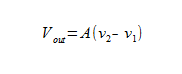
The op amp is designed to detect the difference in voltage applied at the input (the plus (v2) and the minus (v1) terminals, or pins 2 and 3 of the op amp package). The difference is also known as the differential input voltage. The output, then, is the difference sensed at the input multiplied by some value A - the open-loop gain. An op amp behaves as a voltage-controlled voltage source, which we will model now. We will simulate both an open-loop and a closed-loop amplifier configuration.
An ideal op amp has the following characteristics:
- Infinite open-loop gain
- Infinite input resistance
- Zero output resistance
- Zero common-mode gain = infinite common mode-rejection
- Infinite bandwidth
- Zero noise
- Zero input offset
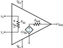
Because the input resistance (Rin) is infinite, we can deduce that the current seen at the (+)(v2) and (-)(v1) terminals are zero, using Kirchhoff's laws. Since the output resistance (Rout) is zero, there is no voltage loss at the output. The diamond-shaped voltage source in the image above is known as voltage-dependent voltage source, and in this case the voltage is the gain (G) multiplied by the difference between the input terminals (Vin). The gain is normally referred to as (A) in texts, so the equation for the output is given by:
Let's model a voltage-controlled voltage source and see if we can't get its behavior to mimic an ideal op amp.
Feedback with Amplifiers
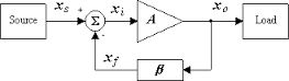
Op amps are not meant to be used as stand-alone devices. We simply verified the Vout equation in the ideal op amp video to show why it is commonly referred to as a voltage-controlled voltage source. We are going to talk about feedback and closed-loop gain and application. What is feedback? Feedback occurs when the output of a system is fed back into as input(s). There are two types of feedback: positive (regenerative) and negative (degenerative). Feedback is applied to the system to affect one or more of the following properties:
- Desensitize the gain - the value of the gain becomes less sensitive to variations in the values of the circuit component, such as temperature effects on transistors.
- Reduce non-linear distortion - the output is proportional to the input.
- Reduce the effect of noise - reduces the amount of unwanted electrical interference on the output. This interference could be external or from the circuit components themselves.
- Control the input and output resistances - with an appropriate feedback configuration the input and output resistances can be controlled.
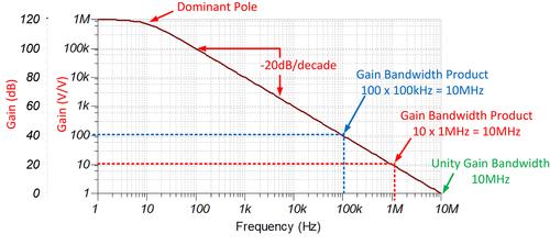
- Extend the bandwidth of the amplifier. We need to be aware of the Gain-Bandwidth Product here. You can extend the bandwidth (to a certain degree) but at the cost of the gain. Gain Bandwidth Product is constant and describes the op amp gain behavior with respect to frequency.
Quick Note about Units
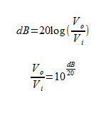
When were talking about gain, we are taking the ratio of the output to the input. If both output and input are expressed in terms of voltage then the units will be Volt/Volt. In the .ac analysis the gain is given in terms of decibels. Here's the conversion formula.
All of the feedback comes at a price, and that cost is the gain. Negative feedback trades gain for more desirable properties; increasing the input resistance also increases the bandwidth.
Closed-Loop Gain
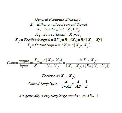
Unlike open-loop gain, the closed-loop gain is dependent on the external circuitry because of the feedback. However, it can be generalized.
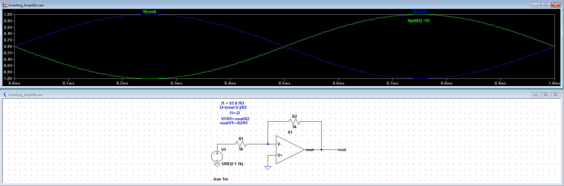
Inverting Amplifiers
An example of an inverting configuration consists of one op amp and two resistors, R1 and R2. R2 is connected from the output terminal of the op amp to the inverting or minus terminal of the op amp. R2 closes the loop around the op amp.
One thing not mentioned in the video below, but is considered implied because we are still using the ideal op amp, is that no current flows through the op amp. All the current (I1) flowing through R1 is also flowing through R2. Another thing to note is that if R1 and R2 are equal in value then this circuit is typically used convert -vout to +vout (changes the phase). This is known as the unity-gain inverter.
Project: The Summing Amplifier
A typical application for an inverting amplifier is a summing amplifier, also known as a virtual earth mixer, used in audio mixing. I happen to have quite a few LM741 op amps lying around, so I went ahead and built a summing amplifier. First I modeled it in LTSpice.
Non-Inverting Amplifiers
The Voltage Follower
The voltage follower is a nice example of a non-inverting amplifier. The property of very high input impedance is a desirable feature of the non-inverting configuration. The voltage follower can used as a unity-gain buffer amplifier connected from a high impedance source to a low impedance source - this helps to avoid loading effects on the driving circuit.
Difference Amplifiers
Difference amplifiers respond to the difference between two signals applied at its input, and rejects signals that are common to the two inputs.
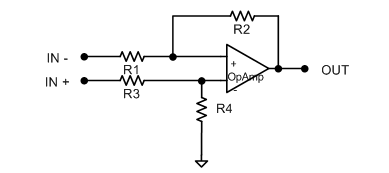
A Single Op Amp Difference Amplifier
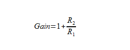
Remember that the gain of a non-inverting amplifier is positive and is given by:
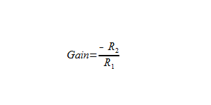
and that the gain of an inverting amplifier is negative and is given by:
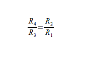
By combining these two topologies we are getting closer to be able to design a circuit that will be able to obtain the difference between the two input signals. In order to accomplish this, we must first make sure the gain magnitudes (think absolute values that are always positive) of each are equal. By attenuating the gain of the positive path from (1+ R2/R1) to (R2/R1), we've done exactly that. We now have four resistors; we need to make sure the gains are equal so the ratio of the resistors is important:
The problem with this circuit is that in order to obtain high gain, R1 must be relatively low. This causes the input resistance to drop. Another issue is that it isn't easy to vary the gain of this amplifier. Both of these issues are solved with the implementation of the instrumentation amplifier. Using three op amps, we can get a fine-tuned differential amplifier. Since we have the problem of low input resistance using one op amp, we can add an additional voltage follower or buffer at each input. Even more awesome is that the buffers can add to the gain, easing the burden on the difference amplifier in the second stage.
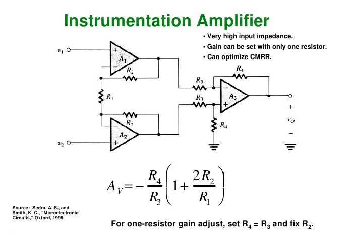
The instrumentation amplifier perfectly combines all the previous material: inverting and non-inverting amplifiers in cascade.
We will not cover integrators, differentiators, oscillators or AD converters in this tutorial. Once we start adding capacitors and inductors, the math gets a bit more specialized and generalized in terms of impedance rather than resistance. These will be a separate tutorial.
Performance Characteristics
If we look at a data sheet for the LM386 audio amplifier, we'll see a ton of parameters that help characterize the op amp. Most of these can be verified with simulation in LTSpice. Before we can get there let's define some of these characteristics.
Common Mode Rejection Ratio
Common mode rejection ratio (CMRR) measures the amount of signal common to both inputs that is not amplified. It is desirable for the common mode gain to be very low, which corresponds with a very high CMRR.
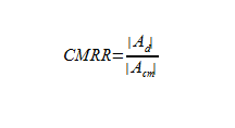
The common mode rejection ratio is the ratio of the absolute value of differential gain to the absolute value of the common mode gain. The differential gain is typically half the intrinsic gain of the MOS transistor set by the manufacturer. Op amps with high output resistance will feature the best CMRR.
Power Supply Rejection Ratio
Power Supply Rejection Ratio or PSRR is the measure of the influence of the power supply ripple on the op amp output voltage. PSSR is important to MOSFET devices as they are usually on mixed-signal ICs where the digital switching in the circuit causes increased power supply ripple. The last thing you want in your design is to have that ripple amplified through your op amp.
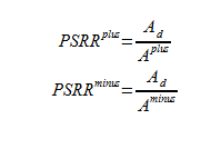
The takeaway here is that to minimize the effects of ripple in power supplies, the Op Amp is required to have a large PSRR. So keep that in mind when looking at data sheets for any upcoming projects.
Slew Rate
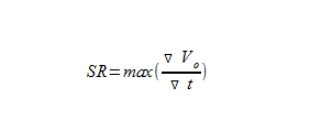
Slew rate refers to the maximum rate of change possible at the output of an op amp. Most op amps are slew rate-limited, and that is calculated by taking the max of the derivative, with respect to time of the output voltage of the op amp.
Total Harmonic Distortion
The task of an audio amplifier is to take a small signal and amplify it without making any changes other than amplifying it. This is a difficult task because unwanted signals (i.e. ripple) may be amplified along with the desired signal. Any deviation from linearity is considered a distortion. Harmonic distortion is a common form of distortion in audio applications where the peaks of the output signal get "clipped." The lower the percentage listed for THD the better, but after a certain point it is hardly perceptible to human ears.
The LM386 Audio Amplifier
Simulate, verify, build – my motto. In this case, the mini portable guitar amp project case, I took it too far. I couldn't find a model I could import into LTSpice and I started from scratch. Below is a button where you can download the project files for what I am about to show you. I designed an op amp based on the LM386, but with MOSFETs instead of BJTs. I actually got this design to slightly out-perform the part I based my design off of, but it only works from 2 to 6 volts. Even though my LM386 model is not exactly like the part used in the project, it is still practical for looking at the electrical characteristics of op amps and getting more familiar with LTSpice.
Project: Mini Portable Guitar Amplifier
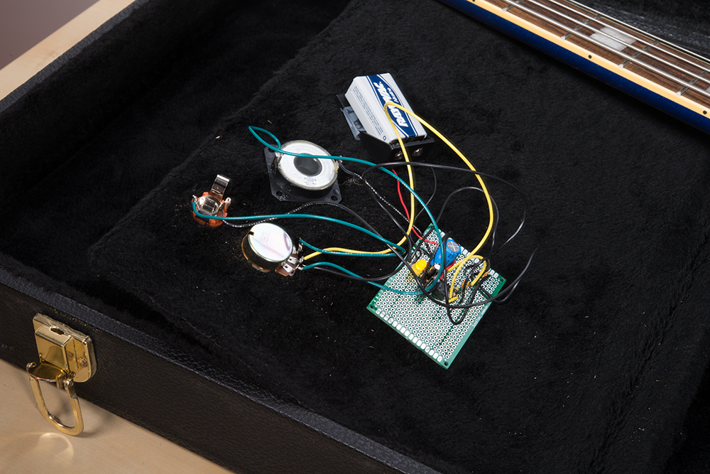
I built a small, battery-powered amplifier into the case of my guitar using the LM386 and minimal extra parts. The whole build cost about $5.00 and took less than an hour to put together. The circuit I took directly from the data sheet applications section (Gain of 200):
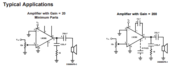
The only changes I made were to the output capacitor. I didn't have a 250uF capacitor handy to I swapped it out for a 470uF. I also added the 1/4" mono audio female receptacle for the guitar cable and added a status LED so I knew when I was ready to rock. My guitar case has a little cubby for cables and picks so I used that space to build the amplifier into.
Schematic:
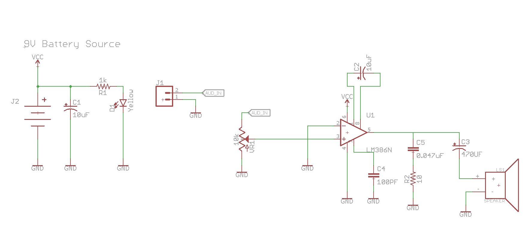
Note: J1 is the 1/4" female mono audio jack receptacle.
See it in action:
Resources and Going Further
The Virtual Op Amp Lab:
Music from Outer Space creator Ray Wilson made this MFOS Virtual Operational Amplifier Application, which allows us to experiment with op amps while viewing the output on a simulated oscilloscope.
Music From Outer Space
Ever wanted to get into DIY-synths but don't know where to start? Music From Outer Space is a great resource offering hundreds of schematics designed by Ray Wilson.
Hobbyists
If you are just getting into analog electronics projects, I cannot recommend Forrest Mims' Engineer's Mini Notebooks enough.
Measuring CMRR
EE Times has a fantastic article about common mode rejection ratio and differential amplifiers.