Assembly Guide for SparkFun JetBot AI Kit
This Tutorial is Retired!
While the hardware assambly instructions for the original (beta) version of the Jetbot are still valid; the software instructions are not. Please refer to our latest tutorial, linked below:
View the updated tutorial: Assembly Guide for SparkFun JetBot AI Kit V2.0
4. Accessory Installation to Main Chassis
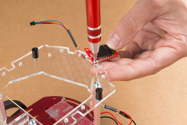
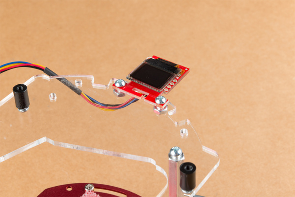
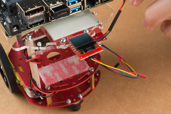
Align the mounting holes on the SparkFun Micro OLED (Qwiic) with those on the back of the SparkFun Jetbot acrylic mounting plate. Install the Micro OLED using two 1/4 in 4-40 Phillips head screws and two 4-40 machine screw nuts.
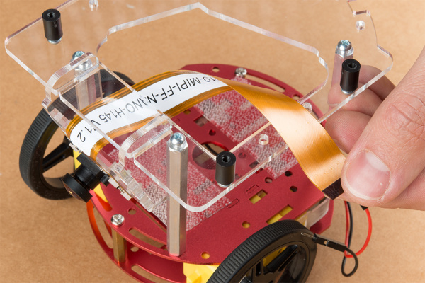
Thread the ribbon cable of the Leopard imaging camera back through the acrylic mounting plate and half-helix towards the left side of the Jetbot.
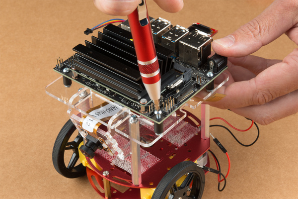
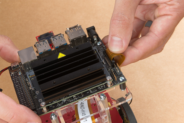
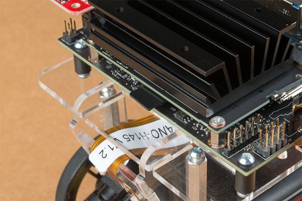
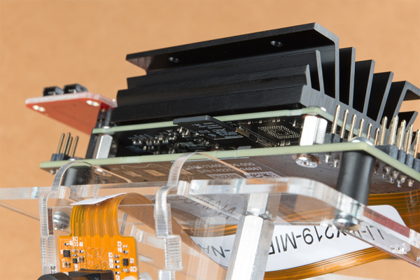
Install the Jetson Nano Dev kit to the nylon standoffs using four 1/4 in 4-40 Phillips head screws. Tighten each screw slightly in a criss-cross pattern to ensure the through holes do not bind during install until finger tight. Make sure you can still access the camera ribbon cable.
Note: the camera connector is made from small plastic components & can break easier than you think. Please be careful with this next step.Loosen the camera connector with a fingernail or small flathead screwdriver. Fit the ribbon cable into this connector and depress the plastic press fit piece of the connector to hold the ribbon cable in place.
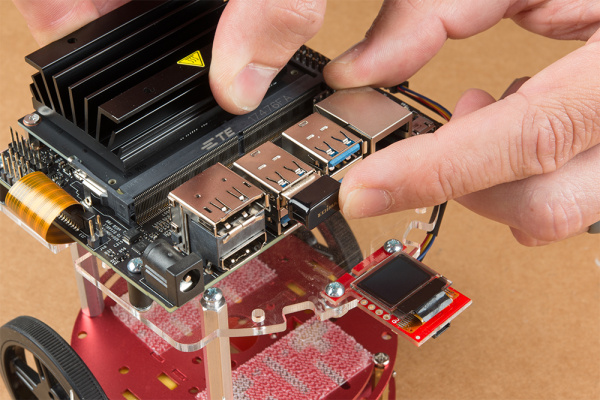
Unpackage & install the USB Wifi adaptor into one of the USB ports on the Jetson nano Dev Kit. The drivers for this Wifi adaptor are pre-installed on the SparkFun Jetbot image. If you are making your own image, you will need to ensure you get these from Edimax.
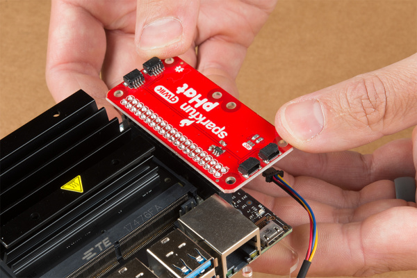
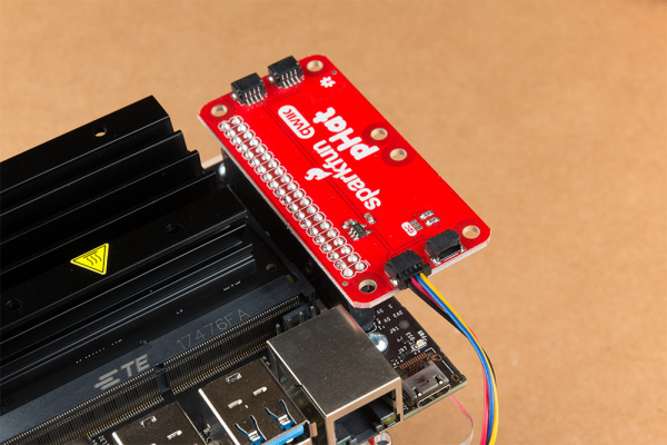
Align the SparkFun pHat with the GPIO headers on the Jetson Nano Dev Kit so that the pHat overhangs the right hand side of the Jetbot. For additional information on hardware assembly of the SparkFun pHat, please reference the hookup guide here.
Note: The heatsink on the Jetson Nano Dev Kit will only allow for one orientation of the SparkFun pHat.
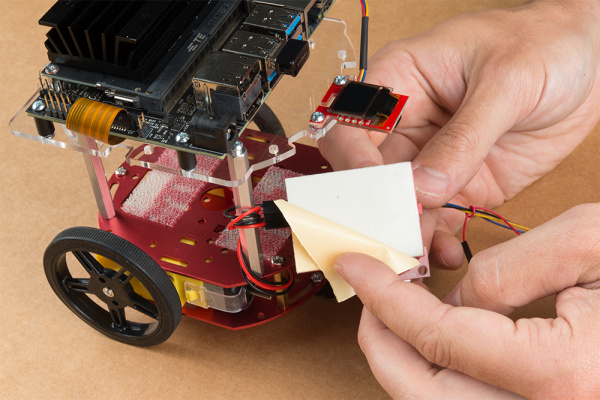
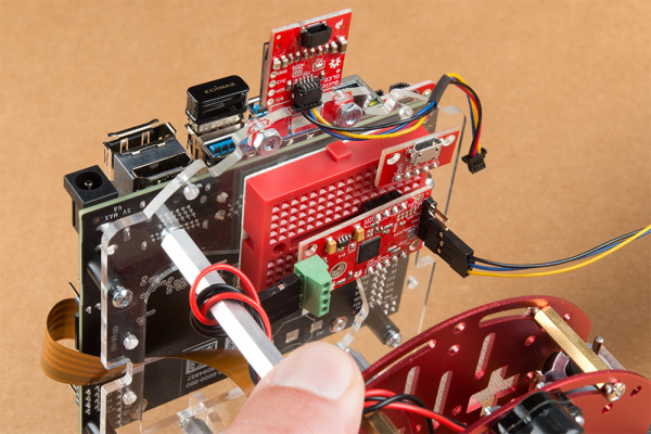
Wrap the motor wires around the rear/left standoff to take up some of the slack; one or two passes should do. Peel the cover off the self adhesive backing on the mini breadboard you set aside at the end of section #3.
Place the breadboard near the back of the Jetbot Acrylic mounting plate where there is good adhesion & access to all the components. Attach the (4-pin) Female Jumper Qwiic cable to the SparkFun Serial Controlled Motor Driver pins as shown. Yellow to "SCL," Blue to "SDA," Black to "GND."
Daisy chain the polarized Qwiic connector on the other end of the (4-pin) Female Jumper Qwiic cable into the back of the SparkFun Micro OLED (Qwiic).
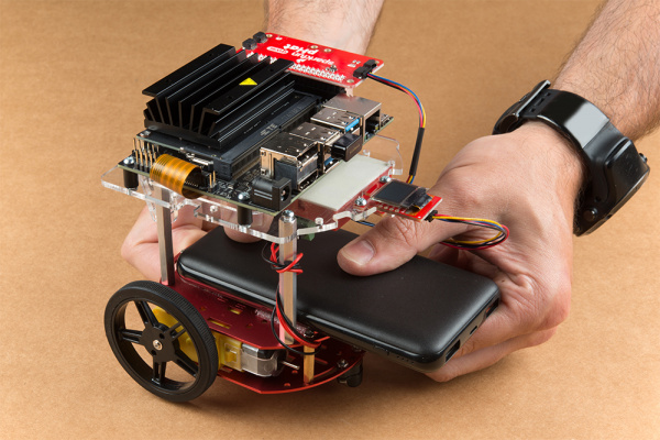
Using the 100mm Qwiic Cable attach the SparkFun Micro OLED front Qwiic connector to the SparkFun pHat as shown.
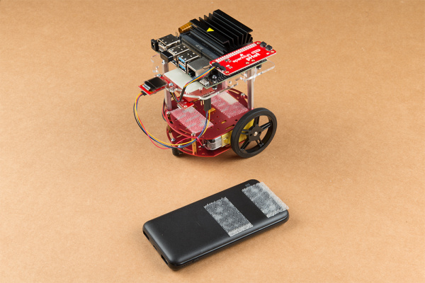
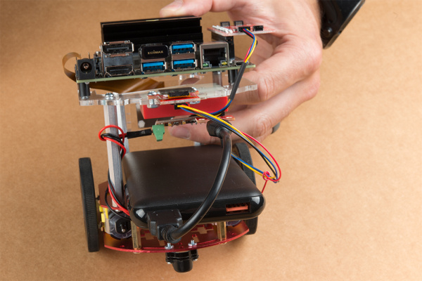
Cut the Dual Lock Velcro into two pieces and align them on the 10Ah battery & top plate of the Two-Layer Circular Robotics Chassis as shown below. Ensure that the USB ports on the battery pack are pointing out the back of the Jetbot. Additionally, the orange port (3A) will need to power the Jetson Nano Dev Kit & therefore will need to be on the right side of the Jetbot.
Apply firm pressure to the battery pack to attach to the Jetbot chassis via the Dual Lock Velcro.
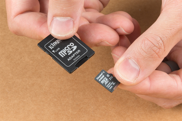
Remove the micro SD card from the SD card adapter.
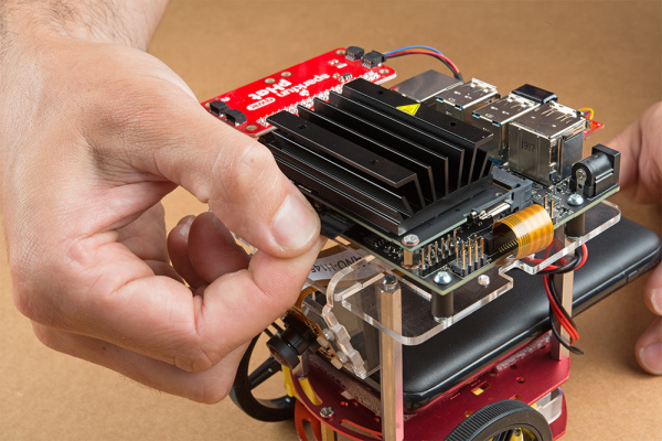
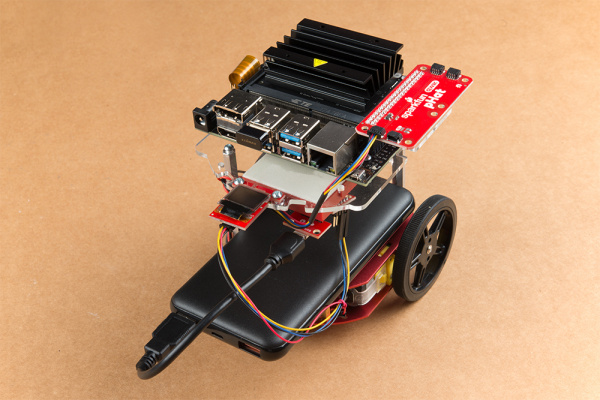
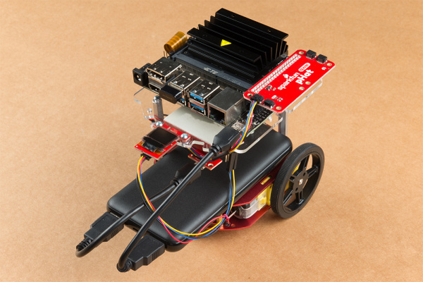
Insert the micro SD card facing down into the micro SD card slot on the front of the Jetson Nano Dev Kit. Please see the next three pictures for additional details.The USB ports on the back of the 10Ah battery pack has two differently colored ports. The black port (1A) is used to power the motor driver via the SparkFun microB breakout. Utilize one of the 6 in micro-B USB cables to supply power to the microB breakout.
Note: Once you plug the Jetson Nano Dev Kit into the 3A power port, this will "Boot Jetson Nano" which is not covered in detail until the links in section #5 of this assembly guide. Do not proceed unless you are ready to move forward with the software setup & examples provided by NVIDIA.
The orange port (3A) is used to power the Jetson Nano Dev Kit. Utilize the remaining 6 in micro-B USB cable to supply power to the Jetson Nano Dev Kit.
Congratulations! You have fully assembled your SparkFun JetBot AI Kit!
