Assembly Guide for SparkFun JetBot AI Kit
This Tutorial is Retired!
While the hardware assambly instructions for the original (beta) version of the Jetbot are still valid; the software instructions are not. Please refer to our latest tutorial, linked below:
View the updated tutorial: Assembly Guide for SparkFun JetBot AI Kit V2.0
 Evan_Double_U
3. Motor Driver Assembly & Configuration
To get started, make sure that you are familiar with the SparkFun Serial Controlled Motor Driver Hookup Guide.
We also recommend a detailed review of the Hardware Overview of the SparkFun Serial Controlled Motor Driver Here.

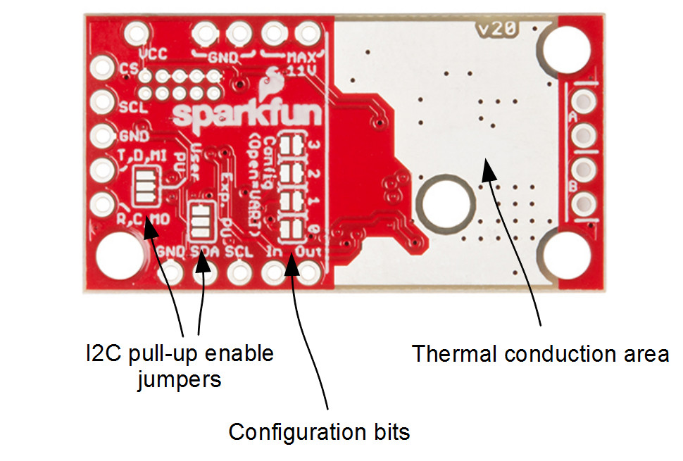
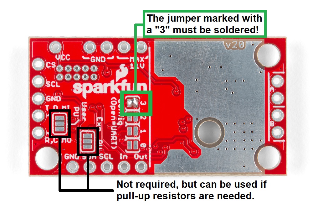
You will need to solder both triple jumpers labeled below as "I2C pull-up enable jumpers" as the SparkFun pHat utilizes the I2C protocol. The default I2C address that is used by the pre-flashed SparkFun Jetbot image is 0x5D which is equavalent to soldering pad #3 noted as "configuration bits" on the back of the SparkFun serial controlled motor driver; see below. You will need to create a solder jumper on pad #3 only for the SparkFun Jetbot Image to work properly.
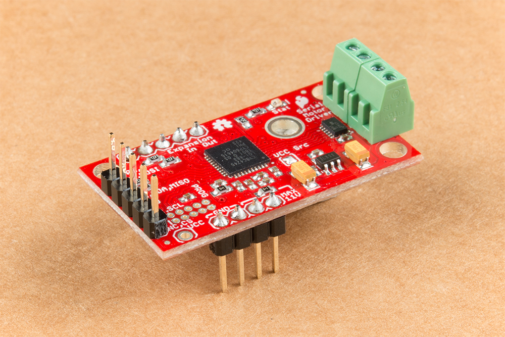
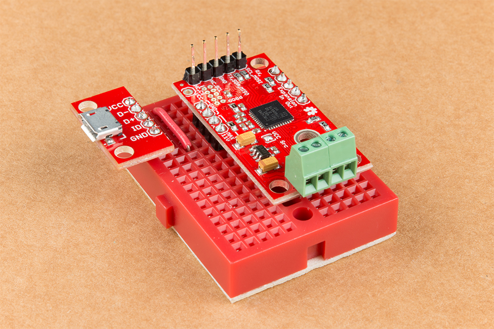
Your completed Serial Controlled motor drive should look somewhat similar to the board shown below.
- The 2-pin screw terminals are soldered to the "Motor Connections."
- Break off 4 Male PTH straight headers and solder into the "Power (VIN) connection" points.
- Break off 5 Male PTH straight headers and solder into the "Expansion port" points. These will not be used, but will provide additional board stability when installed into the mini breadboard.
- Break off 5 Male PTH straight headers and solder into the "User port" points for connection into the included Female Jumper Qwiic cables.

Break off 5 Male PTH straight headers and solder into the breakout points on the SparkFun microB USB Breakout.
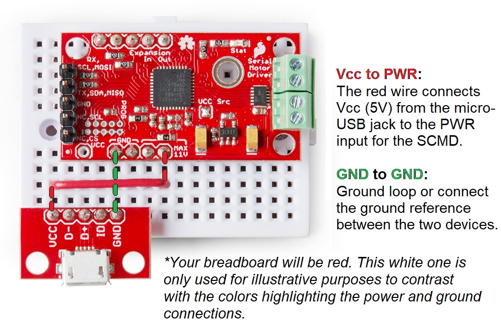
Install both the SparkFun Serial Controlled Motor Driver & the SparkFun microB Breakout board on the included mini breadboard so the "GRD" terminals for each unit share a bridge on one side of the breadboard.
Utilize the included 2 in - 22 gauge solid core hookup wire (red) to bridge the "VCC" pin for the SparkFun microB Breakout to either (VIN) connection point on the SparkFun Serial Controlled Motor Driver as shown below.
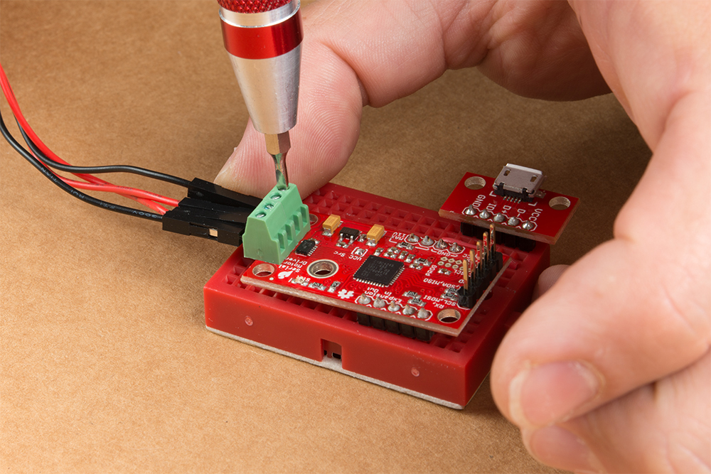
Utilize a small flat head screwdriver to loosen the four connection points on the screw terminals. When inserting the motor connection wires, note the desired output given the caution noted in section #1 of this assembly guide.
Note from section #1: Do not worry about the motor orientation as you will determine proper motor operation in how you connect the motor leads to the SparkFun Serial Controlled Motor Driver.
These connection points can be corrected when testing the robot functionality. If your Jetbot goes straight when you expect Jetbot to turn or vice versa, your leads need to be corrected.
Set this assembly aside for full installation later.