Assembly Guide for SparkFun JetBot AI Kit
This Tutorial is Retired!
While the hardware assambly instructions for the original (beta) version of the Jetbot are still valid; the software instructions are not. Please refer to our latest tutorial, linked below:
View the updated tutorial: Assembly Guide for SparkFun JetBot AI Kit V2.0
 Evan_Double_U
1. Circular Robotics Chassis Kit (Two-Layer) Assembly
If you prefer to follow along with a video, check out this feature from the chassis product page. You do not need to use the included ball caster as a larger option has been provided for smoother operation.
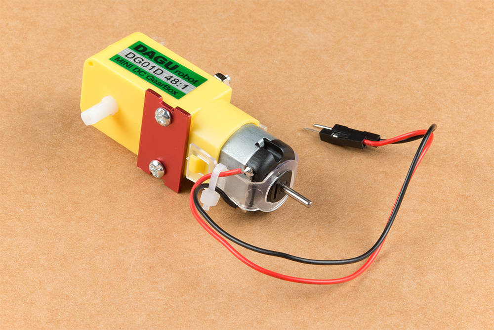
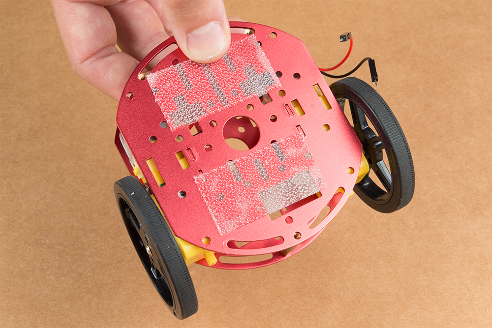
Start by attaching the chassis motor mount tabs to each of the "Shadow Chassis Motors (pair)" using the long threaded machine screws & nuts included with the Circular Robotics Chassis Kit.


The motor mounts fit into two mirrored inlets in each base plate as shown. Install the motors opposite of one another.
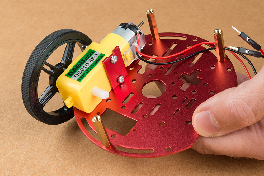
Depending on how you install the motor mounts to each motor will dictate how the motor can be installed on the base plate. Note: Do not worry about the motor orientation as you will determine proper motor operation in how you connect the motor leads to the SparkFun Serial Controlled Motor Driver. Notice how in the picture below one motor has the label facing up, while the other has the label facing down.
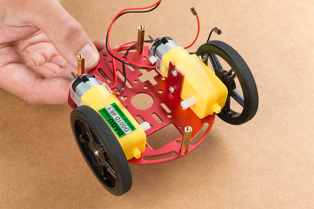
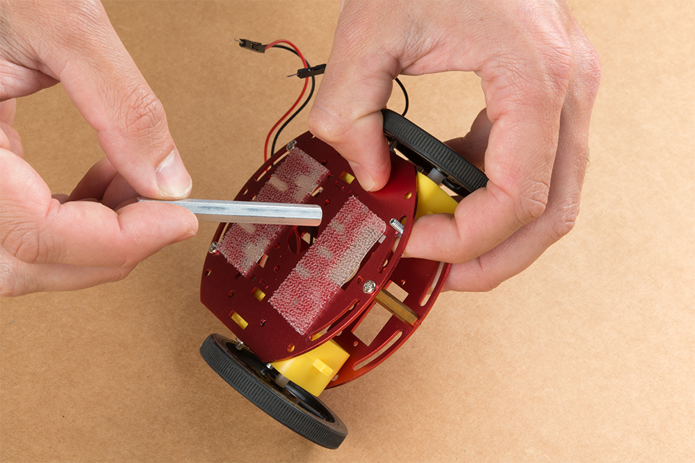
Place the other circular robot chassis plate on top of and align the two "+" and the motor mount tab recesses. Hold the sandwiched chassis together with one hand and install the remaining Phillips head screws included with the Circular Robotics Chassis Kit through the top plate & into the threaded standoffs.
Your main chassis is now assembled! The Circular Robotics Chassis Kit also contains a very small caster wheel assembly, but we have included a larger metal caster ball to increase the stability of the SparkFun Jetbot. We will cover the installation of this caster ball later in the tutorial.

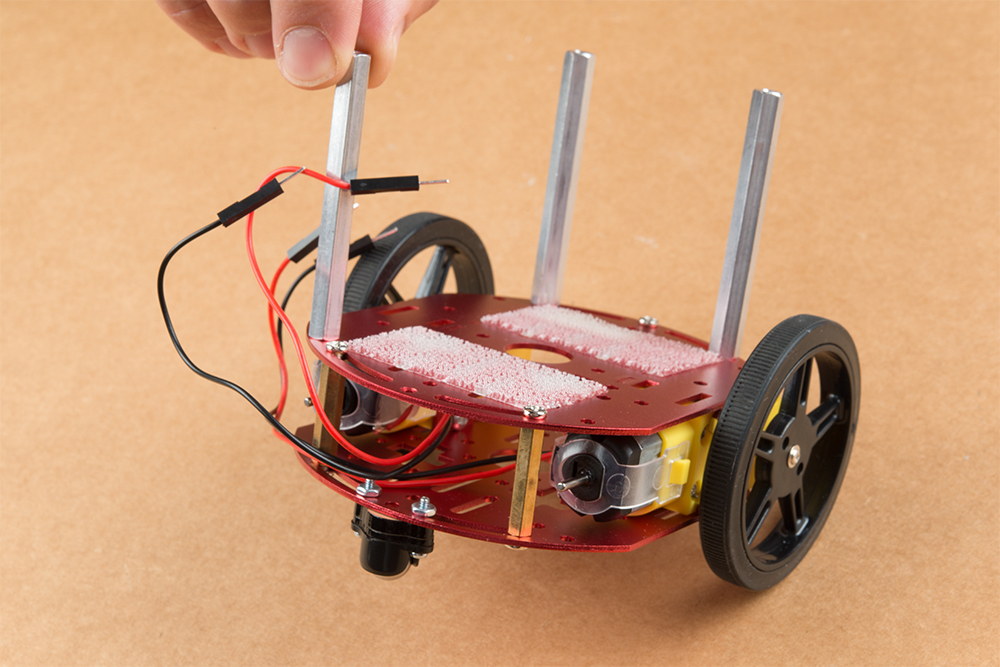
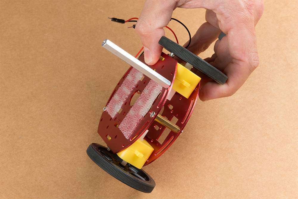
Utilize three of the included 1/4 in 4-40 Phillips Screws through the top chassis plate with threads facing up & install the 2-3/8 in #4-40 Aluminum Hex Standoff until they are finger tight.
The aluminum stand offs should be pointing up as shown below.
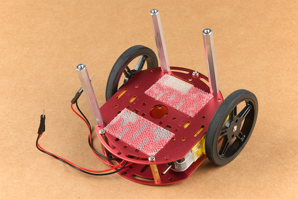
The SparkFun JetBot acrylic mounting plate is designed to have two of these aluminum standoffs in the front & one in the rear. We recommend the rear standoff on the left side of the chassis (as shown) so the 6 in microB usb cables that will be installed later can more easily span the gap needed to power the JetBot.
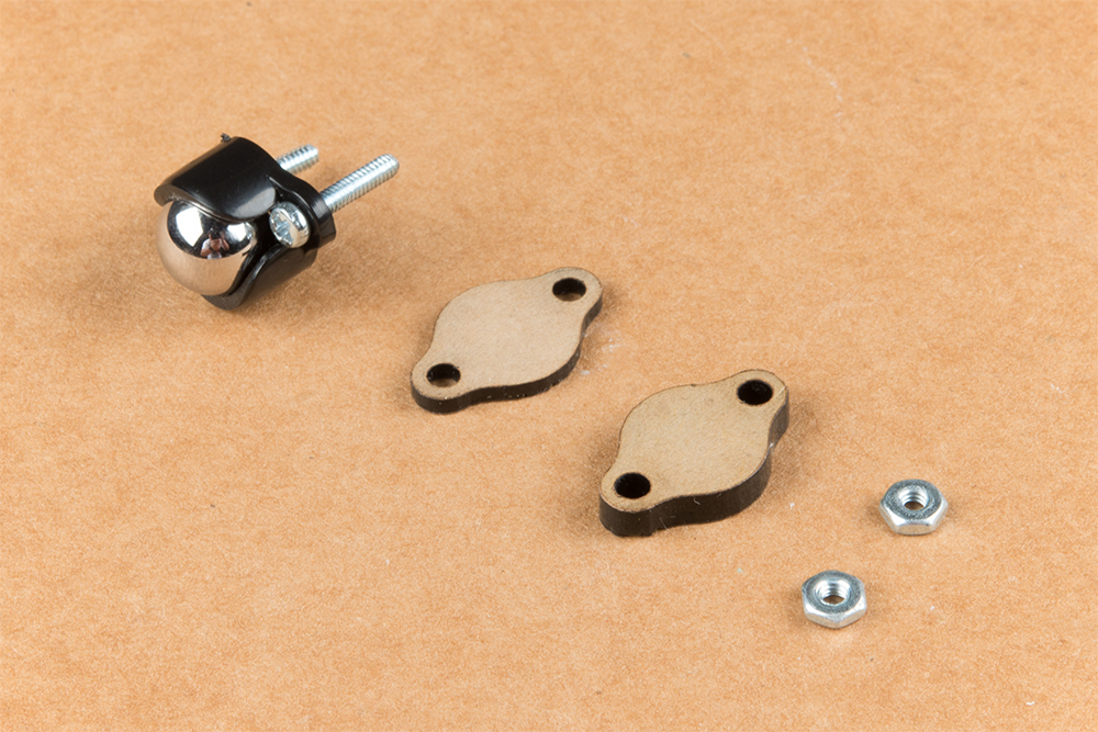
Un-package the 3/8 in Metal Caster Ball and thread the mounting screws through all pieces as shown. Note the full stack height will help balance the Jetbot in a stable position.
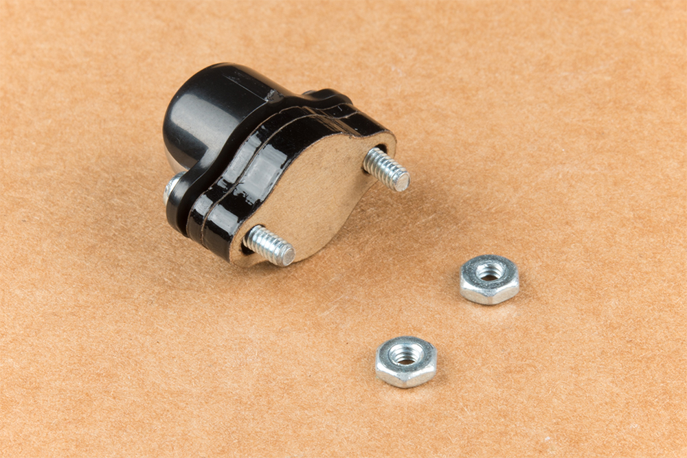
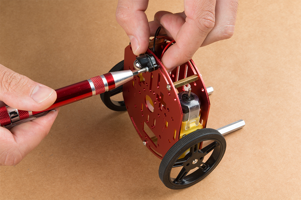
Install the caster wheel using the Phillips head screws and nuts included with the 3/8 in caster ball assembly. The holes on the caster assembly are spaced to fit snug on the innermost segment of the angular slots near the rear of the lower plate on the JetBot chassis. Again, hand tight is just fine. Note: if you over tighten these screws it will prevent the ball from easily rotating in the plastic assembly. However, too loose and it may un-thread; go for what feels right
After you have installed the caster & aluminum standoffs, thread the motor wires through the back of the chassis standoffs for use later.