Artemis Global Tracker Hookup Guide
 QCPete,
  El Duderino
 Introduction
The SparkFun Artemis Global Tracker provides a powerful tracking system combining remote short messaging via the Iridium satellite network with GPS tracking and environmental sensing all powered by the SparkFun Artemis module. The Global Tracker design focuses on truly remote tracking, data collection and transmission so whether you're looking to transmit environmental data from the top of a mountain, send data from a traveling balloon, control and monitor remote equipment or maybe communicate in an emergency when other networks are not available; the Artemis Global Tracker may be just the right tool for your remote data project.
Required Materials
The Artemis Global Tracker (or AGT as we'll sometimes refer to it in this guide) requires a few external components to get up and running properly. First and foremost is a power supply. The AGT receives power via either USB-C, single-cell LiPo battery or an external solar panel or battery pack (max 6V). Take a look at the products below for power supply options for the AGT:
USB-C


LiPo Battery


Lithium Ion Battery - 1Ah
PRT-13813
Solar Panel
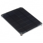
Solar Panel - 2W
PRT-13781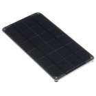
Solar Panel - 3.5W
PRT-13782
Solar Panel - 6W
PRT-13783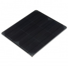
Solar Panel - 9W
PRT-13784Antenna
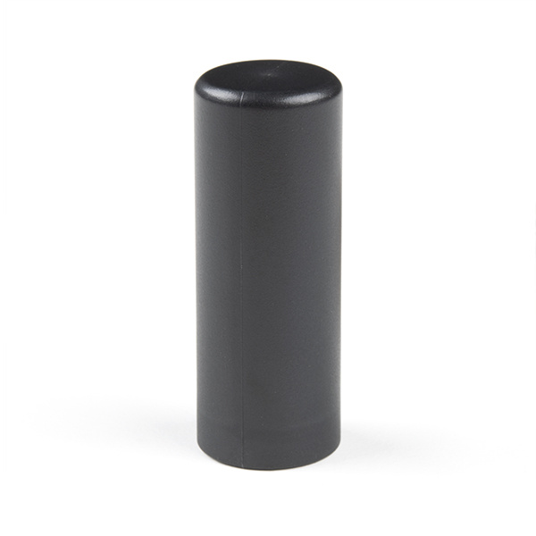
The AGT also requires an external antenna for the 9603N and M8Q modules. The AGT routes both modules' antenna pins to a shared SMA connector so to keep things simple, we recommend a passive antenna tuned for Iridium/GPS/GLONASS bands like the antenna shown below:
External Capacitors
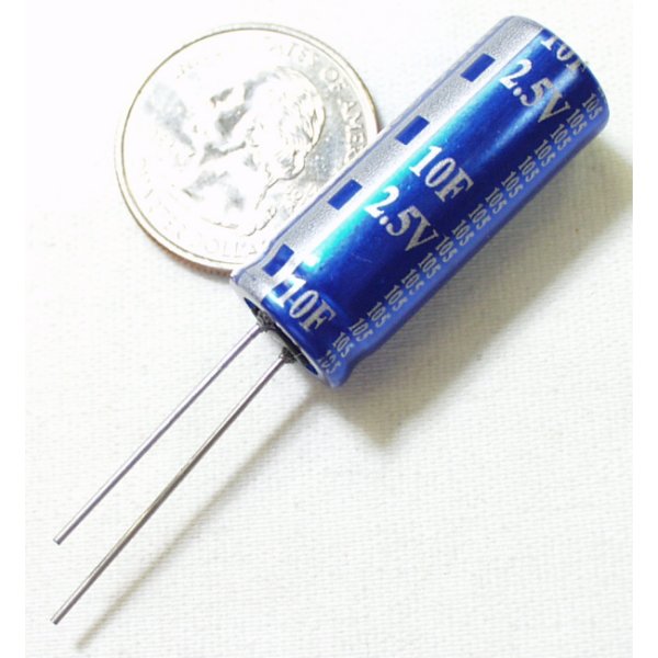
Users powering the Artemis Global Tracker with a solar panel or lower-current power configurations need to attach a pair of external 10F capacitors like the ones below to provide the extra current for 9603N SBD transmissions:
Satellite Network Line Rental
The Iridium modem requires a monthly rental service to exchange information with the Iridium satellite network. Set up an account with Rock7 here. You only pay for months in which you wish to use the modem. No annual contract is required. Line rental costs £12GBP (about $15USD) per month and includes access to the RockBLOCK management system for managing your devices. The billing system is built-in, and allows you to pay for only what you use. Airtime for Iridium modems must be purchased from Rock Seven via the admin portal once the units are registered. You cannot use the devices with another Iridium airtime provider by default. If you would like to use it with another provider, you will need to pay an unlock fee of $60USD per modem.
Recommended Reading
Users who have never used the Artemis module or other Artemis boards may want to read through the following tutorials before getting started with the Artemis Global Tracker:
Three Quick Tips About Using U.FL
Using SparkFun Edge Board with Ambiq Apollo3 SDK
Designing with the SparkFun Artemis
Artemis Development with the Arduino IDE
Installing Board Definitions in the Arduino IDE
Hardware Overview
Let's take a look at the Artemis Global Tracker and all the hardware on it. There is a lot to cover here so buckle up.
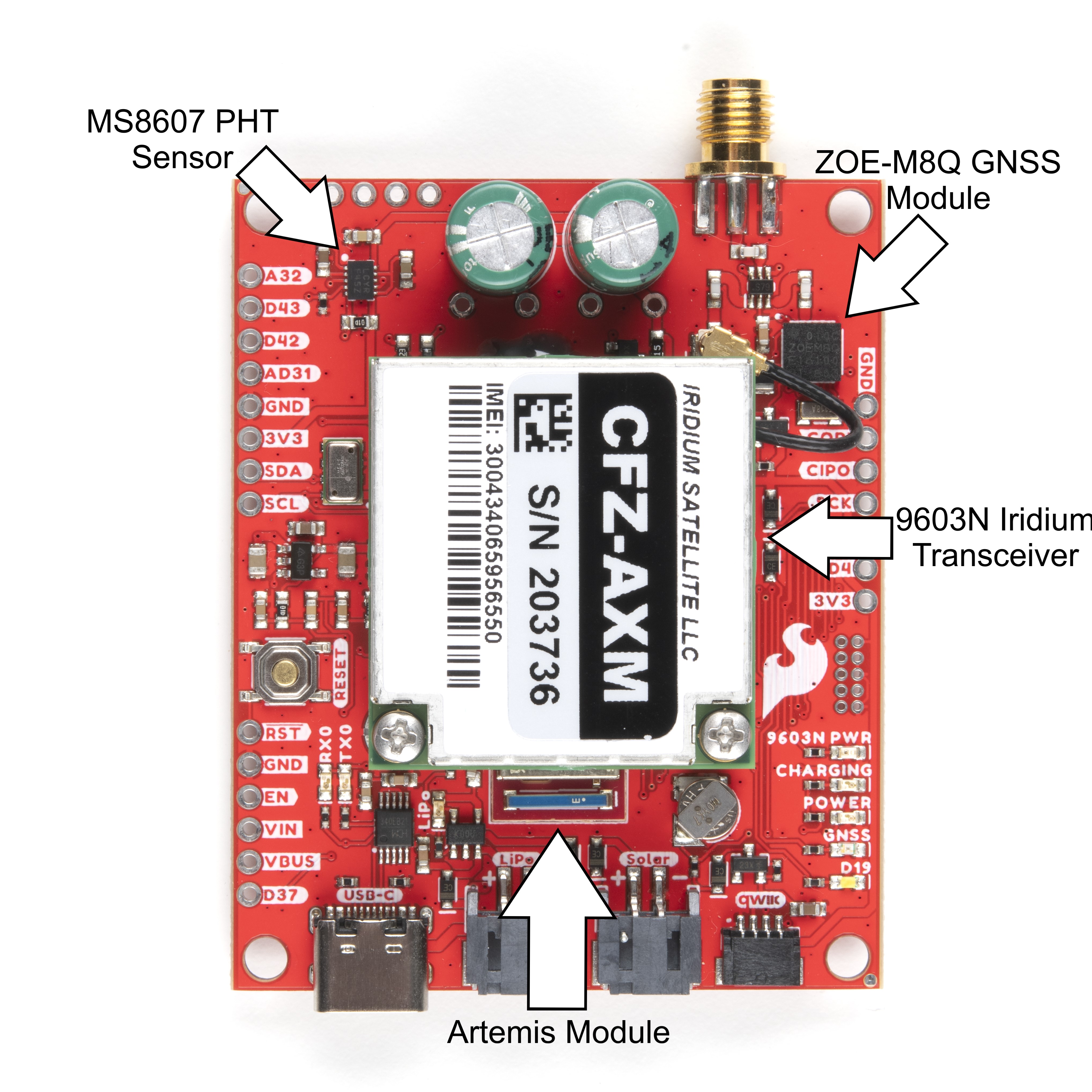
Major AGT Components
The Artemis Global Tracker combines the SparkFun Artemis module, Iridium 9603N Satellite Transceiver, ZOE-M8Q GNSS module and MS8607 PHT sensor to provide location and environmental data to a powerful, low-power processor system capable of transmitting collected data from anywhere on the planet using the Iridium Satellite network. First up we'll cover these major components in more detail.
Artemis Microprocessor
As the name suggests, the SparkFun Artemis Module rests at the core of the Artemis Global Tracker. The Artemis Module is built on the Apollo3 MCU platform and is a Cortex-M4F based module with BLE 5.0 that runs at 48MHz clock frequency (up to 96MHz burst mode) and low-power consumption as low as 6µA per MHz. The Artemis also features plenty of storage space with up to 1MB of Flash memory and up to 384KB RAM, BLE 5 RF sensitivity of -93dBm (typical) and TX peak output power of 4.0dBm. For a complete overview of the Artemis module, please review the Artemis Integration Guide and Graphical Datasheet.
The Artemis works on multiple development platforms; the SparkFun Apollo3 Arduino Core, Python, as well as Ambiq's Apollo3 SDK allowing users to choose which development environment works best for their application. Note, the examples for the Artemis Global Tracker are written for the Arduino IDE.
Iridium 9603N Satellite Transceiver
The AGT uses an Iridium 9603N Satellite Transceiver to take advantage of the Iridium Satellite transmission network to send and receive small data packets in truly remote areas with no WiFi and GSM network coverage. With a clear view of the sky, the Iridium can send short messages anywhere in the world, including polar regions outside the range of traditional wireless networks like WiFi and GSM networks. Refer to the datasheet for more information on the 9603N.
The 9603N is a small form-factor satellite transceiver that uses Iridium's satellite network in Low-Earth Orbit which reduces latency greatly as compared to networks using geostationary satellites. The 9603N design focuses on creating a robust transceiver capable of working in inhospitable environments with an operating temperature range of -40°C to 85°C and up to 75% humidity.
The module draws relatively low current during idle, transmission and receive. Short-Burst-Data transfers require the most current for short periods (8ms) but the design accommodates for that by powering the 9603N with a pair of 1F supercapacitors and charge/current regulation circuit covered in more detail below. The table below shows the typical and max values for each of those operations (all values operating at 5V):
| Operation | Current Draw |
|---|---|
| Idle | 34mA avg. (156mA peak) |
| Transmit | 145mA avg. (1.3A peak) |
| Receive | 39mA avg. (156mA peak) |
| Short-Burst Data Transfer | 158mA avg. |
The AGT ties the 9603N's Shutdown Pin to Artemis pin D17 to allow software control of power to the module. This software control is important to take note of when transmitting data using an antenna attached to the SMA connector as the 9603N shares an antenna connection with the ZOE-M8Q. The AGT includes a switching circuit to select which module uses the antenna as both modules cannot use the antenna at the same time. This circuit defaults to use the ZOE-M8Q antenna line when the device is powered so make sure to power the GNSS module down prior to transmitting data with the 9603N.
ZOE-M8Q GNSS Module
The ZOE-M8Q GNSS module from u-blox adds positional data to the Artemis Global Tracker. The ZOE-M8Q is an ultra-small GNSS module that works with all major GNSS constellations (GPS, GLONASS, Galileo and BeiDou). For a complete overview of the ZOE-M8Q refer to the datasheet. The module also supports up to four circular geofencing areas so you can trigger alarm messages sent over the Iridium network when your device either enters or exits one of those areas.
The AGT uses the ZOE-M8Q's I2C bus to communicate between the module and the Artemis controller. With a passive antenna, the ZOE-M8Q achieves up to 2.5m accuracy with GPS lock. From a cold start, the module has a Time-To-First-Fix of 29s with GPS and a hot start fix time of 1s on all constellations. The table below outlines the ZOE-M8Q's specifications:
| Parameter | Specification | GNSS Constellation | |||||
|---|---|---|---|---|---|---|---|
| GPS and GLONASS | GPS | GLONASS | BeiDou | Galileo | |||
| Horizontal Position Accuracy | --- | 2.5m | 2.5m | 4m | 3m | --- | |
| Max Navigation Update Rate | ROM | 10Hz | 18Hz | 18Hz | 18Hz | 18Hz | |
| Flash | 5Hz | 10Hz | 10Hz | 10Hz | 10Hz | ||
| Time-To-First-Fix | Cold Start | 26s | 29s | 30s | 34s | 45s | |
| Hot Start | 1s | 1s | 1s | 1s | 1s | ||
| Sensitivity | Tracking and Navigation | -167dBm | -166dBm | -166dBm | -160dBm | -159dBm | |
| Reacquisition | -160dBm | -160dBm | -156dBm | -157dBm | -153dBm | ||
| Cold Start | -148dBm | -148dBm | -145dBm | -143dBm | -138dBm | ||
| Hot Start | -157dBm | -157dBm | -156dBm | -155dBm | -151dBm | ||
| Velocity Accuracy | 0.05m/s | ||||||
| Heading Accuracy | 0.3 degrees | ||||||
Power to the ZOE-M8Q is controlled by a P-Channel MOSFET tied to Artemis pin D26. This allows users to turn the module off and on when positioning data is not needed. The board also includes a 1mAh backup battery and charging circuit for the ZOE-M8Q to allow the module to operate in Hardware Backup Mode for up to 12 hours to keep the clock running and allow a hot or warm start later. The backup battery recharges only with USB power connected (to help minimise the 3.3V current draw during sleep).
As a reminder, the ZOE-M8Q shares the antenna connection with the 9603N module. Both modules cannot use the antenna at the same time so the board includes a switching circuit to select which module uses the antenna.
MS8607 PHT Sensor
The Artemis Global Tracker includes the MS8607 Pressure, Humidity and Temperature sensor from TE Connectivity for an integrated environmental monitoring system at your remote station as well an effective altimeter for balloon applications. For a complete overview of the MS8607, refer to the datasheet.
The MS8607 offers a wide operating range with excellent precision for pressure, temperature and humidity. The table below outlines theses parameters.
| Characteristic | Pressure (mbar) | Relative Humidity (%RH) | Temperature (°C) | ||||||
|---|---|---|---|---|---|---|---|---|---|
| Min | Typ | Max | Min | Typ | Max | Min | Typ | Max | |
| Max. Operating Range | 10 | 2000 | 0 | 100 | -40 | +85 | |||
| Absolute Accuracy @25°C | 300...1100mbar | 20...80%RH | @25°C | ||||||
| -2 | 2 | -3 | 3 | -1 | 1 | ||||
| Resolution (Highest Mode) | 0.016 | 0.04 | 0.01 | ||||||
Power
The Artemis Global Tracker includes three power input options in USB-C, single-cell LiPo battery or a solar panel (or battery pack), LiPo charging circuit and a dedicated supercapacitor power and charging circuit for the 9603N.
Primary Power Inputs
Low-forward-voltage diodes isolate the three power inputs from each other so that users can have all three power sources present without harming anything on the AGT. If USB voltage is present (along with other power supplies), the AGT prefers to draw power from USB. If just Solar Cell/Battery Pack and LiPo are connected, the AGT defaults to drawing power from the Solar Cell/Battery Pack input, making the LiPo redundant.
| Power Input | Voltage Range | Notes |
|---|---|---|
| USB-C | 5V | AGT selects USB as power if voltage is present along with other power sources (LiPo/Solar/etc.) |
| LiPo Battery | 4.2-3.0V | Charging circuit only powered with voltage present on USB. |
| Solar Panel | Max 6.0V | Additional 10F capacitors recommended for 9603N module power during transmit cycles. |
| Battery Pack | 3.0-6.0V | 3x Energizer™ Ultimate Lithium AA or AAA cells are recommended for extreme environments as they operate down to -40°C. |
LiPo Battery Charge Circuit
The AGT includes a charging circuit for an attached single-cell LiPo battery using one of our favorite LiPo management controllers, the MCP73831 from Microchip. The charge circuit configuration sets the charge rate to 500mA. The LiPo charging circuit only receives power via VUSB; USB power is required to charge an attached LiPo battery.
Supercapacitors and Charge Circuit
The AGT provides power to the 9603N through a pair of supercapacitors charged by an LTC3225 supercapacitor charger regulated by an ADM4210 in-rush current limit circuit. The charge circuit defaults to source enough current (150mA) to power the 9603N during normal operation and the supercapacitors provide the extra 1.3A required during the Short Burst Data (SBD) transfers (8.3ms).
The charge circuit is configurable to switch to a lower max current (60mA) for low-current power configurations like solar. While in the low max current configuration users need to add a pair of 10F capacitors to provide the extra current required by the 9603N module during normal operation and SBD transfers.
The AGT ties the LTC3225's Shutdown Input pin to Artemis pin D27 which allows users to put the charger into Shutdown Mode to help reduce power consumption when the supercapacitor charge circuit is not needed. Set D27 LOW to put the LTC3225 into Shutdown Mode and reduce current consumption by the charge circuit to approximately 1µA. Users looking for more detailed information on the LTC3225 should refer to the datasheet.
Bus Voltage
The AGT includes a voltage monitoring circuit to keep track of the bus voltage (from the USB, LiPo or external cells). The board uses Artemis pin AD13 for voltage measurement via a simple two resistor divider dividing the bus voltage by three. Power to the resistor divider is switched by an N-channel MOSFET so the power draw can be minimized during sleep.
GPIO PTHs
The AGT breaks out an assortment of helpful GPIO pins from the Artemis module to PTH headers to interface with external devices. The board routes the following: SPI, I2C, Reset, and eleven multi-purpose GPIO pins to PTH headers:
SPI/I2C Bus and Reset PTHs
- SDA
- SCL
- RST
- CIPO
- COPI
GPIO PTHs
- AD11~
- AD12~
- AD29~
- AD31~
- AD32~
- AD35~ (SPI CS1)
- D4~ (SPI CS2)
- D15
- D37*
- D42~
- D43~
- Pins marked with a "~" are PWM-capable.
- I2C pins (SDA and SCL) are shared with ZOE-M8Q and MS8607 @3.3V.
- *D37 is a low-Impedance pin. Useful for controlling MOSFETs to power external devices.
For detailed information on alternate functionality and GPIO multiplexing options, refer to the Designing with the SparkFun Artemis tutorial and Artemis/Apollo3 Pin Function Map.
LEDs
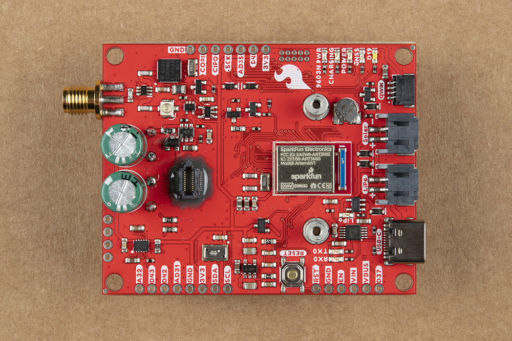
The AGT has seven status LEDs highlighted in the photo below:
- 9603N PWR: Illuminates when the 9603N is powered on.
- CHARGING: Illuminates when the supercapacitor charge circuit is active.
- POWER: Illuminates when 3.3V is present.
- GNSS: Illuminates when ZOE-M8Q is powered on.
- D19: General status LED tied to Artemis D19.
- RX0: UART0 RX data indicator LED.
- TX0: UART0 TX data indicator LED.
Solder Jumpers
The Artemis Global Tracker has four solder jumpers labeled PWR LED, Supercaps Charge Current, 3.3V EN and MEAS.
The PWR_LED jumper allows users to disable the Power LED to help reduce power consumption for low-power applications. This jumper is CLOSED by default. Sever the trace between the two pads to open the jumper and disable the Power LED.
The Supercaps Charge Current Jumper adjusts the maximum current for the LTC3225 Supercapacitor charger by tying the PROG pin to Ground through one of two different valued resistors (12kΩ (default) and 30.1kΩ). By default, it sets the charge current to 150mA, opening the jumper sets the charge current to 60mA. When in this configuration additional capacitors are required to provide the extra power drawn by the 9603N during transmission cycles.
The 3.3V EN Jumper controls the Enable Pin on the 3.3V regulator to VIN. The jumper is CLOSED by default and ties the Enable Pin to VIN. Opening the jumper leaves the Enable Pin tied only to the PTH labeled EN on the AGT allowing users to use that PTH pin to turn the regulator on and off.
The MEAS Jumper allows users to measure the current draw of the AGT. By default, the jumper is CLOSED and nets all three power inputs to VIN.
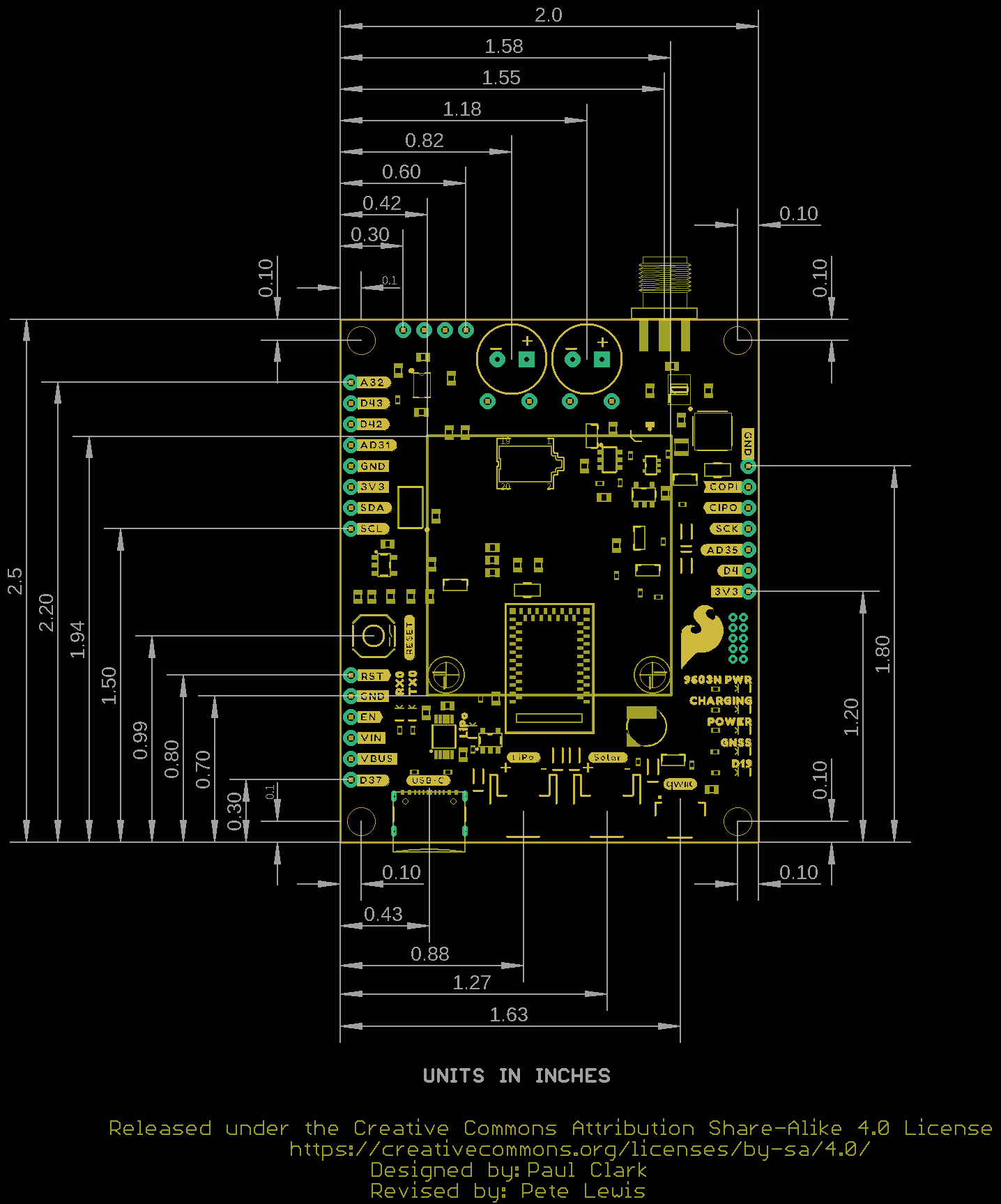
Board Dimensions
The Artemis Global Tracker measures 2.5in x 2.0in (63.5mm x 50.8mm) with four mounting holes that fit a 4-40 screw.
Hardware Assembly
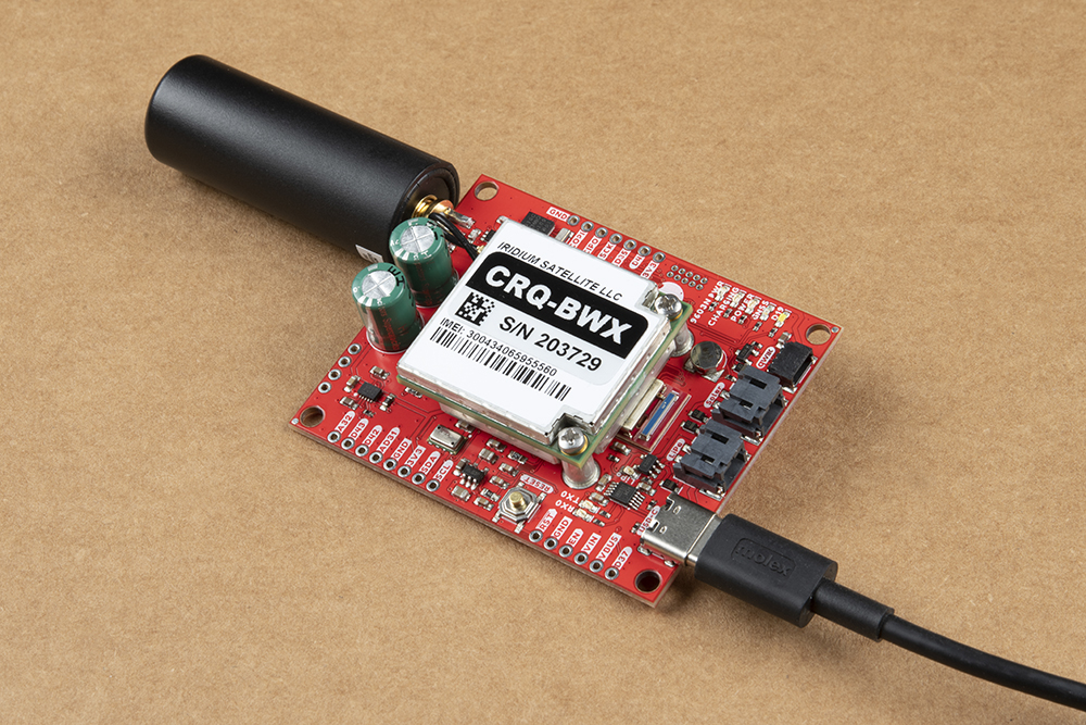
The Artemis Global Tracker comes basically ready-to-use out of the box for most applications. The only assembly required for basic use is to connect an antenna to the SMA connector and attach your power supply (USB, solar panel and/or battery). Users powering the AGT with a solar panel or other low-current supply most likely need to solder additional supercapacitors to the provided PTH connections.
Basic Assembly (USB/LiPo Battery)
Simple assembly of the AGT only requires a power source and antenna connection. On initial setup you'll want to connect it to a computer via USB to program the board. With your preferred code running on the AGT, connect the antenna to the SMA connector and then power it with either a USB power supply, LiPo battery or solar panel/battery pack connected to the properly labeled connection (USB or JST connector). Reminder, the LiPo charging circuit only operates with voltage from USB.
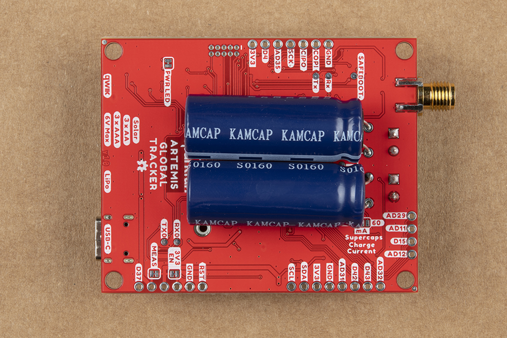
Additional Supercapacitor Assembly
Solar powered or other low-current applications may require users to adjust the Charge Current jumper to set the charge rate from 150mA to 60mA. The reduced current provides enough for the 9603N's 39mA average current draw during receive, but larger supercapacitors are needed to supply the average current pulled during a complete receive/transmit cycle.
Before soldering to the board, remove the 9603N from the AGT by unscrewing the mounting screws, carefully unplug the u.Fl cable and then remove the 9603N from the board making sure to pull directly upwards. After removing the 9603N, turn the board over and solder a pair of additional 10F capacitors like these to the labeled pads on the back of the board taking care to match the polarity:
Iridium and Artemis Software Setup
The Artemis Global Tracker requires a couple of software setup steps users need to complete before they start working with the device. You must create an account for Rock7 Operations to set up line rental and message credits for the 9603N. Users wanting to use the AGT with the Arduino IDE may need to install the SparkFun Apollo3 Arduino core to upload code to the Artemis Module.
Rock7 Operations
Head over to Rock7's Operations webpage to create an account to use the 9603N on the Iridium Satellite Network. You must create an account and link the 9603N to it as well as set up a line rental and purchase message credits with Rock7 to send data over the network. The website has easy-to-follow instructions to get the 9603N registered and operating on the network.
Artemis Arduino Guides
Users needing to install the SparkFun Apollo3 Arduino Core should read through the tutorial below:
Artemis Development with the Arduino IDE
The Artemis Global Tracker uses the Artemis ATP board definitions. The Artemis Arduino Core install includes this board definition but in case you are interested in learning more about the Artemis ATP, head on over to the Hookup Guide:
Hookup Guide for the SparkFun RedBoard Artemis ATP
Artemis Global Tracker Arduino Examples
The AGT ships with a comprehensive Global Tracker example pre-loaded on the board for users to get started quickly with the Artemis Global Tracker Configuration Tool so if you want to skip ahead and use the Configuration Tool, jump ahead to the next section.
Arduino Examples
We've written twenty examples for users to familiarize themselves with all of the hardware present on the Artemis Global Tracker using the Arduino IDE. The examples build on each other to quickly test functionality of different circuits on the AGT and demonstrate how to use the PHT sensor, ZOE-M8Q and 9603N individually with some highlighting features of these components as well as three examples showing how to create a tracking device using the AGT. Download the examples either from the GitHub repository or you can download a ZIP of the GitHub repo by clicking the button below:
Open the examples either from the folder they downloaded to or you can put them in your "Arduino Sketchbook" folder to open them in the Arduino IDE. If you're not certain where your Sketchbook folder is, open the "Preferences" menu in Arduino and look for the filepath under the selection titled "Sketchbook location".
Required Arduino Libraries
The Artemis Global Tracker examples use three SparkFun libraries users need to install prior to working with them:
Install the libraries through the Arduino Library Manager tool by searching for "IridiumSBDi2c", "SparkFun u-blox GNSS Arduino Library" and "SparkFun PHT MS8607 Arduino Library". Users who prefer to manually install the libraries can download the ZIP of each library repository by clicking the buttons below:
Arduino Examples
With the Artemis Arduino Core and necessary libraries installed we can move on to using the examples. This tutorial covers six of the Arduino examples we find most helpful to demonstrate how to use the major components on the AGT and then how to use them all in conjunction to create a global tracking device.
Users looking to write their own code for the AGT should take note of the following pin definitions and functions:
language:c
// D4 can be used as an SPI chip select or as a general purpose IO pin
#define spiCS1              4

// Input for the ZOE-M8Qs PIO14 (geofence) pin
#define geofencePin         10

// Bus voltage divided by 3 (Analog in)
#define busVoltagePin       13

// Iridium 9603N ON/OFF (sleep) pin: pull high to enable the 9603N
#define iridiumSleep        17

// Input for the Iridium 9603N Network Available
#define iridiumNA           18

// White LED
#define LED                 19

// ADM4210 ON: pull high to enable power for the Iridium 9603N
#define iridiumPwrEN        22

// GNSS Enable: pull low to enable power for the GNSS (via Q2)
#define gnssEN              26

// LTC3225 super capacitor charger: pull high to enable the super capacitor charger
#define superCapChgEN       27

// Input for the LTC3225 super capacitor charger PGOOD signal
#define superCapPGOOD       28

// Bus voltage monitor enable: pull high to enable bus voltage monitoring (via Q4 and Q3)
#define busVoltageMonEN     34

// D35 can be used as an SPI chip select or as a general purpose IO pin
#define spiCS2              35

// Input for the Iridium 9603N Ring Indicator
#define iridiumRI           41

void gnssON(void) // Enable power for the GNSS
{
  am_hal_gpio_pincfg_t pinCfg = g_AM_HAL_GPIO_OUTPUT; // Begin by making the gnssEN pin an open-drain output
  pinCfg.eGPOutcfg = AM_HAL_GPIO_PIN_OUTCFG_OPENDRAIN;
  pin_config(PinName(gnssEN), pinCfg);
  delay(1);

  digitalWrite(gnssEN, LOW); // Enable GNSS power (HIGH = disable; LOW = enable)
}

void gnssOFF(void) // Disable power for the GNSS
{
  am_hal_gpio_pincfg_t pinCfg = g_AM_HAL_GPIO_OUTPUT; // Begin by making the gnssEN pin an open-drain output
  pinCfg.eGPOutcfg = AM_HAL_GPIO_PIN_OUTCFG_OPENDRAIN;
  pin_config(PinName(gnssEN), pinCfg);
  delay(1);

  digitalWrite(gnssEN, HIGH); // Disable GNSS power (HIGH = disable; LOW = enable)
}

void setup()
{
  // Configure the I/O pins
  pinMode(LED, OUTPUT);

  pinMode(iridiumPwrEN, OUTPUT); // Configure the Iridium Power Pin (connected to the ADM4210 ON pin)
  digitalWrite(iridiumPwrEN, LOW); // Disable Iridium Power
  pinMode(superCapChgEN, OUTPUT); // Configure the super capacitor charger enable pin (connected to LTC3225 !SHDN)
  digitalWrite(superCapChgEN, LOW); // Disable the super capacitor charger
  gnssOFF(); // Disable power for the GNSS

  pinMode(busVoltageMonEN, OUTPUT); // Make the Bus Voltage Monitor Enable an output
  digitalWrite(busVoltageMonEN, HIGH); // Set it high to enable the measurement
  //digitalWrite(busVoltageMonEN, LOW); // Set it low to disable the measurement (busV should be ~zero)

  analogReadResolution(14); //Set resolution to 14 bit
Example 3 - PHT
The first example we'll take a look at is Example 3 - PHT. This example demonstrates how to interact with the MS8607 PHT Sensor to retrieve pressure, humidity and temperature data from the sensor. The code performs all of the AGT pin definitions and custom functions listed above and initializes the MS8607 on the I2C bus:
language:c
if (barometricSensor.begin(agtWire) == false)
  {
    Serial.println("MS8607 sensor did not respond. Trying again...");
    if (barometricSensor.begin(agtWire) == false)
    {
      Serial.println("MS8607 sensor did not respond. Please check wiring.");
      while(1)
        ;
    }
  }
After initializing the sensor, the code polls for temperature (in °C), pressure (in hPa or mbar) and humidity (in %RH) data from the sensor and prints it out over serial every 500ms. Open the serial monitor with the baud set to 115200 to watch the environmental data print out.
Users who prefer to use an external PHT sensor should refer to Example 4 - External PHT for a demonstration of that application.
Example 5 - GNSS
Example 5 shows how to use the ZOE-M8Q to get GNSS positioning data. Upload the example and open the serial terminal with the baud set to 115200 and input set to Newline. The setup initializes the Wire port and sets the clock speed to 100kHz for optimal performance:
language:c
agtWire.begin();
agtWire.setClock(100000);
Before initializing the ZOE-M8Q, the code waits for a user input to confirm the serial monitor settings are correct. After user input, the code turns the ZOE-M8Q on, waits one second for the module to power up, initializes it on the I2C bus, and sets it to output only UBX data:
language:c
Serial.println(F("Please check that the Serial Monitor is set to 115200 Baud"));
Serial.println(F("and that the line ending is set to Newline."));
Serial.println(F("Then click Send to start the example."));
Serial.println();
while(Serial.available() == 0)
;

gnssON(); // Enable power for the GNSS
delay(1000); // Let the ZOE power up

if (myGNSS.begin(agtWire) == false) //Connect to the u-blox module using pads 8 & 9
{
    Serial.println(F("u-blox GNSS not detected at default I2C address. Please check wiring. Freezing."));
    while (1)
        ;
}

//myGNSS.factoryDefault(); delay(5000); // Uncomment this line to reset the ZOE-M8Q to the factory defaults

//myGNSS.enableDebugging(); // Uncomment this line to enable helpful debug messages on Serial

myGNSS.setI2COutput(COM_TYPE_UBX);
The main loop checks for the GNSS fix and prints out what type of fix the module has (Dead Reckoning, 2D, 3D or GNSS+Dead Reckoning). Once the ZOE-M8Q has a GNSS fix the code pulls and prints out latitude, longitude and altitude data from the module.
The two commented out lines allow the user to reset the ZOE-M8Q to factory defaults and enable serial debugging. Sending the factory default command can help recover the ZOE-M8Q in case it gets stuck in an unresponsive state. Enabling serial debugging tells the ZOE-M8Q to send all debug data over serial for troubleshooting.
Example 6 - Geofence
Example 6 builds on the previous example to set up four geofence areas for the ZOE-M8Q to monitor. The code sets everything up just like the previous GNSS example. When the module finds a 3D fix, the code prints the longitude and latitude, creates settings for the four geofence areas, clears any existing geofences stored and then sets four geofence areas of 5m, 10m, 15m and 20m:
language:c
uint32_t radius = 500; // Set the radius to 5m (radius is in m * 10^-2 i.e. cm)
byte confidence = 2; // Set the confidence level: 0=none, 1=68%, 2=95%, 3=99.7%, 4=99.99%
byte pinPolarity = 0; // Set the PIO pin polarity: 0 = low means inside, 1 = low means outside (or unknown)
byte pin = 14; // ZOE-M8Q PIO14 is connected to the geofencePin

Serial.print(F("Clearing any existing geofences. clearGeofences returned: "));
Serial.println(myGNSS.clearGeofences());

Serial.print(F("addGeofence for geofence 1 returned: "));
Serial.println(myGNSS.addGeofence(latitude, longitude, radius, confidence, pinPolarity, pin));

radius = 1000; // 10m
Serial.print(F("addGeofence for geofence 2 returned: "));
Serial.println(myGNSS.addGeofence(latitude, longitude, radius, confidence, pinPolarity, pin));

radius = 1500; // 15m
Serial.print(F("addGeofence for geofence 3 returned: "));
Serial.println(myGNSS.addGeofence(latitude, longitude, radius, confidence, pinPolarity, pin));

radius = 2000; // 20m
Serial.print(F("addGeofence for geofence 4 returned: "));
Serial.println(myGNSS.addGeofence(latitude, longitude, radius, confidence, pinPolarity, pin));
The main loop monitors the state of the four geofences and prints out both the combined and individual status of the geofences every second:
language:c
geofenceState currentGeofenceState; // Create storage for the geofence state

boolean result = myGNSS.getGeofenceState(currentGeofenceState);

Serial.print(F("getGeofenceState returned: ")); // Print the combined state
Serial.print(result); // Get the geofence state

if (!result) // If getGeofenceState did not return true
{
Serial.println(F(".")); // Tidy up
return; // and go round the loop again
}

// Print the Geofencing status
// 0 - Geofencing not available or not reliable; 1 - Geofencing active
Serial.print(F(". status is: "));
Serial.print(currentGeofenceState.status);

// Print the numFences
Serial.print(F(". numFences is: "));
Serial.print(currentGeofenceState.numFences);

// Print the combined state
// Combined (logical OR) state of all geofences: 0 - Unknown; 1 - Inside; 2 - Outside
Serial.print(F(". combState is: "));
Serial.print(currentGeofenceState.combState);

// Print the state of each geofence
// 0 - Unknown; 1 - Inside; 2 - Outside
Serial.print(F(". The individual states are: "));
for(int i = 0; i < currentGeofenceState.numFences; i++)
{
if (i > 0) Serial.print(F(","));
Serial.print(currentGeofenceState.states[i]);
}

byte fenceStatus = digitalRead(geofencePin); // Read the geofence pin
digitalWrite(LED, !fenceStatus); // Set the LED (inverted)
Serial.print(F(". Geofence pin (PIO14) is: ")); // Print the pin state
Serial.print(fenceStatus);
Serial.println(F("."));

delay(1000);
The on-board LED is configured to illuminate when the AGT is inside the combined geofence areas and will go out when the AGT is outside them to provide a visual indicator for quickly identifying the geofence area limits.
Example 10 - Basic Send
Example 10 demonstrates how to perform a basic data transmission using the 9603N to send the classic "Hello, world!" over the Iridium satellite network. The code declares the IridiumSBD object with the sleep (ON/OFF) and RI (Ring Indicator) pins and creates two functions to set up and control Artemis Serial1 to communicate with the 9603N modem:
language:c
IridiumSBD modem(Serial1, iridiumSleep, iridiumRI);

void IridiumSBD::beginSerialPort() // Start the serial port connected to the satellite modem
{
  diagprint(F("custom IridiumSBD::beginSerialPort\r\n"));

  // Configure the standard ATP pins for UART1 TX and RX - endSerialPort may have disabled the RX pin

  am_hal_gpio_pincfg_t pinConfigTx = g_AM_BSP_GPIO_COM_UART_TX;
  pinConfigTx.uFuncSel = AM_HAL_PIN_24_UART1TX;
  pin_config(D24, pinConfigTx);

  am_hal_gpio_pincfg_t pinConfigRx = g_AM_BSP_GPIO_COM_UART_RX;
  pinConfigRx.uFuncSel = AM_HAL_PIN_25_UART1RX;
  pinConfigRx.ePullup = AM_HAL_GPIO_PIN_PULLUP_WEAK; // Put a weak pull-up on the Rx pin
  pin_config(D25, pinConfigRx);

  Serial1.begin(19200);
}

void IridiumSBD::endSerialPort()
{
  diagprint(F("custom IridiumSBD::endSerialPort\r\n"));

  // Disable the Serial1 RX pin to avoid the code hang
  am_hal_gpio_pinconfig(PinName(D25), g_AM_HAL_GPIO_DISABLE);
}
After uploading the code, open the serial monitor with the baud set to 115200. The code waits for the user to open the serial monitor and press send before continuing with the rest of the sketch. After the input, the code enables the supercapacitor charger, begins the charge cycle and then attempts to initialize the 9603N once the charge cycle is complete. Serial prints accompany all these functions for users to follow along with.
Assuming the 9603N initialized correctly, the code checks the signal quality, prints out a value between 0 and 5 (5 being the strongest signal quality) and then attempts to send a text message of "Hello, world!" over the network. This may take several minutes, if the message was sent successfully, the code prints "Hey, it worked!" otherwise, the code prints "Try again with a better view of the sky.".
Regardless of success or failure of sending the text message, the code finishes by clearing the Mobile Originated message buffer, puts the 9603N to sleep and then disables power to the 9603N and supercapacitor charge circuit. Note, this code is not a loop and if it fails, you'll need to reset the AGT before attempting again.
Example 16 - Global Tracker
The last example this tutorial combines everything together to provide a comprehensive global tracker capable of receiving a host of settings updates either via USB-C or wirelessly using Iridium SBD messages. This means users can monitor and configure the device depending on the application's needs while the AGT is in the field.
The example gets a 3D fix from the ZOE-M8Q, environmental readings from the MS8607, measures the bus voltage, and transmits the data at a set interval via Iridium SBD messages. The code also stores many settings in EEPROM (Flash) to be configured either via the USB port or an Iridium binary message sent from Rock7 Operations.
On top of all that, the example includes the capability for users to add up to eight custom functions for additional sensor or other devices in use with the AGT. For those curious about the message format, please review this page in the GitHub repository.
The code defaults to send a text message every five minutes of the following data fields:
- DATETIME: GNSS date and time in YYYYMMDDHHMMSS format
- LAT: GNSS latitude in degrees
- LON: GNSS longitude in degrees
- ALT: GNSS altitude above mean sea level in meters
This example works in tandem with the Artemis Global Tracker Configuration Tool we cover in the next section.
Artemis Global Tracker Configuration Tool
The Artemis Global Tracker Configuration Tool lets users quickly update a host of settings on the AGT while running the Global Tracker Arduino Example either locally using a USB-C connection or remotely via Iridium messages.
Artemis Global Tracker Configuration Tool
The AGT Configuration tool provides a helpful GUI (Graphical User Interface) for users to pick and choose what information the AGT sends in its update messages, message format, and various alarm messages. The AGT ships with Example 16 - Global Tracker running on the board to let you use the Configuration Tool out of the box. Note, the AGT must be running this example for the Configuration Tool to function. Users looking to modify the example to add their own functions should note the example allows for adding up to eight custom functions to interact with using the Configuration Tool.
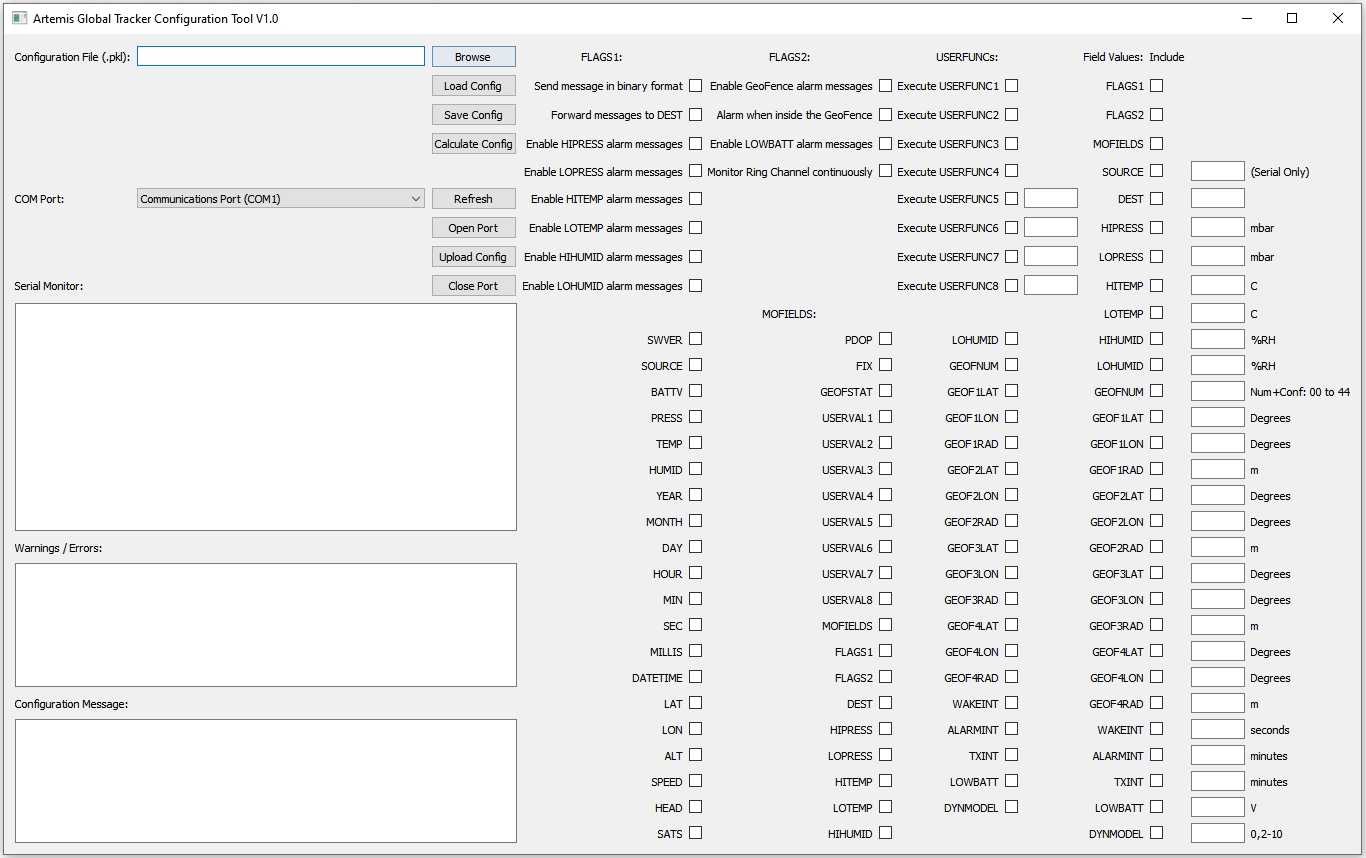
The Configuration Tool is available both as a Python script and Windows executable (.exe). Users familiar with Python and able to install PyQt5 along with all other required modules can run AGTCT.py otherwise users can run the tool as an executable on Windows 64-bit systems. Both versions of the tool are hosted on the GitHub repository in the "Tools" folder and function identically on the front end user interface.
Configuration Tool Options
The Configuration Tool offers a lot of options to customize the data sent by the AGT. Users can customize everything from data sent in messages, various alarm messages ranging from environmental readings, Geofence positions to battery voltage and even custom functions users can write into the Global Tracker Example. Users curious about the message format can read about it on this page in the GitHub repository.
Local Configuration Tool Updates
For local updates, start off by plugging the AGT to your computer with a USB-C cable and take note of the COM port the device enumerates on. Open the Configuration Tool, select your port and click the "Open Port" button. (If you do not see the correct port, click the Refresh button and retry.) You should see a welcome message in the Serial Monitor window with the firmware version after opening the port.
Remote Configuration Tool Updates
Remote configuration using Iridium messages follows nearly the same steps as local configuration. Before selecting the settings in the Configuration Tool, go ahead and log into your Rock7 Operations account. Next, open the Configuration Tool (if it is not open already) and go through the steps to create the configuration files as you would normally do but without opening a port. Once you are ready, click the "Calculate Config" button and you should see a long hex string in the "Configuration Message" window. Select the entire message and copy it.
With the message copied, go to your Rock7 Operations and click on the "Send a message" tab. Make sure to select "Mode Hex" and then paste the configuration message into the "Hex String" window. Select the RockBLOCK serial number for the tracker(s) you want to update and click "Send Message". This saves the settings and stores them for the next time the AGT sends a message.
Artemis Global Tracker Mapping Tools
We also have a suite of Mapping Tools hosted on the GitHub Repository to allow users to track up to eight AGT devices using Google Maps Static API. For more information on these tools and how to use them, refer to this page in the GitHub repository.
Troubleshooting
This tutorial covered a lot so in this section we'll revisit a few troubleshooting tips for the Artemis Global Tracker included in this guide.
Arduino Examples
The Arduino Examples provide the quickest way to troubleshoot most common problems with the AGT. We've done our best to have dedicated examples to most circuits on the board to test everything from the bus voltage to low power mode along with testing the PHT sensor, ZOE-M8Q and 9603N. We recommend any users experiencing issues with their AGT start with these examples to help narrow down and potentially resolve the issue.
Compile Errors
If you experience any compilation or upload errors in Arduino, make sure you are using version 2.1.0 of the Apollo3 Arduino core. Once the latest version of that core has no issues with the AGT Arduino Examples we'll update this section.
Insufficient Power for 9603N SBD Transmission
As a reminder, power configurations using a solar panel or other low-current power supply need to have an additional pair of 10F capacitors soldered to the indicated PTH pads. Solar panels cannot typically provide sufficient current to run the supercapacitor charge circuit at 150mA and we recommend adjusting the Charge Current jumper to set the charge current to 60mA.
Iridium Line Rental and Credits
In order to send and receive messages on the Rock7 network users must set up an account on Rock7, purchase a line rental and credits from Rock7.
Example 10 Message Lost
You may find when running Example 10 (or other messaging examples if you skip Example 10) the message does not arrive at the endpoints/delivery group on first try. We found this message can get "lost" on first use with a new modem. If you do not receive the message on the endpoint, try running the example again and it should send the message. Note, you should not be charged any credits for the first "lost" message.
Antenna Signal
One of the most common causes of issues with both the ZOE-M8Q GNSS transceiver and 9603N modem is antenna signal. If either of these components have issues with receiving or sending data, make sure the antenna has a clear view of the sky away from large objects like buildings or large trees.
Also, remember to only power the 9603N or ZOE-M8Q individually to prevent conflicts using the shared antenna. While the AGT includes a protection circuit to prevent both devices from using the antenna at the same time, the circuit prioritizes the ZOE-M8Q antenna over the 9603N so if both are powered on, only the ZOE-M8Q will have an antenna connection.
General Troubleshooting and Technical Assistance
If you need technical assistance and more information on a product that is not working as you expected, we recommend heading on over to the SparkFun Technical Assistance page for some initial troubleshooting.
If you don't find what you need there, the SparkFun Forums are a great place to find and ask for help. If this is your first visit, you'll need to create a Forum Account to search product forums and post questions.
Resources and Going Further
If you made it this far, congratulations! Your Artemis Global Tracker should be fully configured and ready to transmit data from anywhere on Earth. For more information about the AGT or the components on it, please refer to the resources below:
Artemis Global Tracker Documentation
Artemis Module Documentation
- Apollo3 Datasheet (PDF)
- Ambiq
- Artemis Integration Guide (PDF)
- Designing with the SparkFun Artemis
- Artemis Development with Arduino
- Arduino Core
- Artemis Info Page
- Artemis Forums
Iridium 9603N Transceiver Documentation
- 9603N Datasheet (PDF)
- RockBLOCK 9603 Home Page
- Rock7 Operations
- SparkFun IridiumSBD I2C Arduino Library
u-blox M8Q Documentation
- ZOE-M8Q Datasheet (PDF)
- ZOE-M8Q Integration Manual (PDF)
- Product Summary
- SparkFun u-blox GNSS Arduino Library
- u-center Software
MS8607 PHT Sensor Documentation
Looking for some inspiration on what to use the Artemis Global Tracker for? Have a listen to this interview with Jean Rabault from the Norwegian Meteorological Institute who is using the AGT to track sea ice in the polar regions: