Artemis Development with the Arduino IDE
 Liquid Soulder, Member #1571936
SPI: BME680 Environmental Sensor
The SPI pins are useful connecting to peripheral devices, with high-speed communication. In this example, let's use the SparkFun Environmental Sensor Breakout - BME680 and the SPIDemo example from the library provided for the product. Additional, materials like hookup wire and soldering equipment will be required.
Users will need to follow the hookup guide to install the associated Arduino libraries. Once the library is installed, select the SPIDemo example from the File > Examples > BME680 > SPIDemo menu. Refer to the board's hookup guide to verify the pins utilized for the SPI library; the example code may need to be adapted.
Wiring
Users will need to follow the hookup guide to connect the sensor properly. Soldering the appropriate SPI connections using some hookup wire.
Operation: Serial Monitor
This example outputs sensor values to the serial monitor, through the USB connection of the associated board. Follow the steps for programming the associated board to see the code in action.
Once the board is programmed, open the serial monitor on the Arduino IDE; make sure to set the baud rate to 9600 baud. The environmental sensor readings should be be displayed on the Serial Monitor.
Configuring Peripheral SPI Ports/Pins
In order for users to understand how to adapt their code to configure the peripheral SPI ports, we have provided the following example for the Apollo3 core: File > Examples > Apollo3 > SPI.
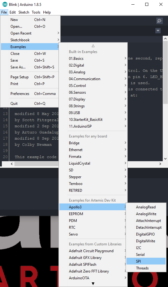
SPI example for the Apollo3 core. (Click to enlarge)