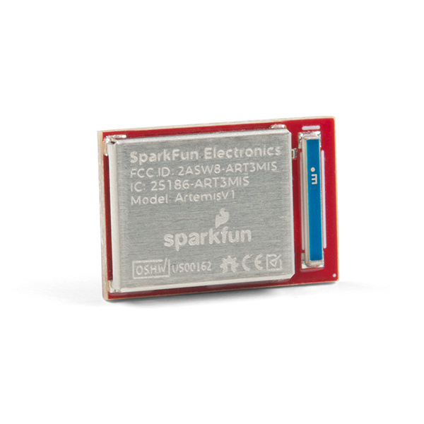
The SparkFun Artemis is an amazing module. So much functionality packed into a tiny 10x15mm footprint! But what really makes it powerful is the ability to quickly write sketches and build projects using only Arduino code. However, for more industry oriented programmer, it is also compatible with Arm® Mbed™ OS. Whether you are using one of our boards that has the Artemis module pre-integrated or have your own, this tutorial will get you started with the Arduino IDE and familiarize you with the various interfaces of the Artemis module.
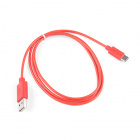
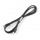
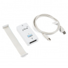
This is a 1m long USB 2.0 Type C to Type C cable with a 100W current rating.
Retired
Programming Firmware
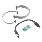
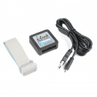
Users interested in flashing their module will need an ARM Programmer and need to solder on a JTAG header. We recommend these programmers from our catalog:
How do I install a custom Arduino library? It's easy! This tutorial will go over how to install an Arduino library using the Arduino Library Manager. For libraries not linked with the Arduino IDE, we will also go over manually installing an Arduino library.
How do I install a custom Arduino board/core? It's easy! This tutorial will go over how to install an Arduino board definition using the Arduino Board Manager. We will also go over manually installing third-party cores, such as the board definitions required for many of the SparkFun development boards.
What is an interrupt? In a nutshell, there is a method by which a processor can execute its normal program while continuously monitoring for some kind of event, or interrupt. There are two types of interrupts: hardware and software interrupts. For the purposes of this tutorial, we will focus on hardware interrupts.
Get our powerful Artemis based boards (Artemis Nano, BlackBoard Artemis, and BlackBoard Artemis ATP) blinking in less than 5 minutes using the SparkFun Artemis Arduino Core!
Do I Need Drivers?
Driver Compatibility: Make sure that the driver for the CH340 is up to date; the serial-to-UART chip may require the latest driver to operate properly. For instructions for updating your driver, please refer to the tutorial below.
Some of our development boards utilize a WCH CH340C or CH340G UART-to-serial chip. A driver should not be required for Mac OSX, Linux, Windows 10; however, we do have a driver installation tutorial available for users.
How to install CH340 drivers (if you need them) on Windows, Mac OS X, and Linux.
The rest of our development boards utilize an NXP interface chip with DAPLink. A driver is not required for Mac OSX, Linux, Windows 10; however, there is a serial port driver available for Windows 7 (only), which is provided by Mbed™. Further instructions and details on installing the serial port driver can be found in the Mbed™ OS documentation.
(*As the Mbed™ OS documentation is continually updated, so are the links. Therefore, users may find it useful to look under the Tutorials > Serial Communication section of the (updated) Mbed™ OS documentation for the serial port driver information.)
Setting up the Arduino IDE
Installing the Arduino IDE
Note: For first-time users, who have never programmed before and are looking to use the Arduino IDE, we recommend beginning with the SparkFun Inventor's Kit (SIK), which includes a simpler board like the Arduino Uno or SparkFun RedBoard and is designed to help users get started programming with the Arduino IDE.
Most users will be familiar with the Arduino IDE and it's use. As a point of reference for professional developers who aren't aware, the Arduino IDE is an open-source development environment, written in Java, that makes it easy to write code and upload it to a supported board. For more details, feel free to check out the Arduino website.
To get started with the Arduino IDE, check out the following tutorials:
How do I install a custom Arduino library? It's easy! This tutorial will go over how to install an Arduino library using the Arduino Library Manager. For libraries not linked with the Arduino IDE, we will also go over manually installing an Arduino library.
How do I install a custom Arduino board/core? It's easy! This tutorial will go over how to install an Arduino board definition using the Arduino Board Manager. We will also go over manually installing third-party cores, such as the board definitions required for many of the SparkFun development boards.
Installing the Apollo3 Board Definitions
Note: The Arduino core for the Apollo3 (i.e. the board definitions) is only compatible up to release 1.8.12. We are currently looking into the issue.
Users will need to install the SparkFun Apollo3 Boards board definitions in the Arduino IDE for our development boards with an Artemis module. Please use the guide below, to get started with installing the SparkFun Apollo3 core for the Artemis modules:
How do I install a custom Arduino board/core? It's easy! This tutorial will go over how to install an Arduino board definition using the Arduino Board Manager. We will also go over manually installing third-party cores, such as the board definitions required for many of the SparkFun development boards.
Otherwise, users can check out this tutorial on Installing Additional Cores provided by Arduino. Users will also need the .json file for the SparkFun Apollo3 Arduino Core:
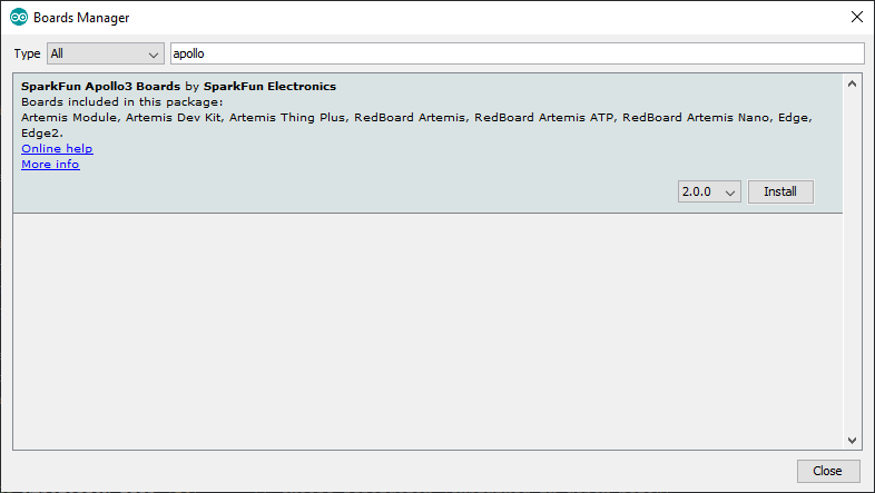
Once, the .json file has been added to the Additional Boards Manager URLs, search for Apollo3 in the Boards Manager.
SparkFun Apollo3 Boards listed in the Boards Manager. (Click to enlarge)
To complete the installation process, selected the SparkFun Apollo3 Boards core and click on the INSTALL button that appears in the lower, right-hand corner. The board definition along with the associated libraries and example sketches will be installed automatically. (*Make sure that the Apollo3 Arduino core is at least version 2.0.0.)
SparkFun's Apollo3 boards and examples listed in the Arduino IDE. (Click to enlarge)
Installing the BLE Library
For users interested in the BLE functionality of the Apollo3 and Artemis boards, we have provided full support to the Arduino BLE library. Additional details about the library can be referenced from the documentation provided by Arduino.
Users will need to install the Arduino BLE library to take advantage of that functionality; please use the guide below, to get started with installing the Arduino BLE library:
How do I install a custom Arduino library? It's easy! This tutorial will go over how to install an Arduino library using the Arduino Library Manager. For libraries not linked with the Arduino IDE, we will also go over manually installing an Arduino library.
Programming the Artemis Module
Users should refer to the hookup guide for their board for the programming procedures. However, below is a summary of the available methods:
Drag and Drop Method
Development boards that utilize an NXP interface chip with DAPLink with appear as a mass storage device for drag-and-drop programming. The interface chip will accept a .hex or .bin file that is compiled for that specific board and program the Artemis module accordingly.
Drag-and-drop programming for the Artemis Development Kit. (Click to enlarge)
Serial Upload w/ ASB or SVL Bootloader
Known Issue: With the latest v2.0.0 Apollo3 Arduino core, there is an issue uploading sketched using the SVL.
Users can use the ASB to workaround this issue; however, it is recommended that users be aware of that there seems to be some sort of issue when uploading with the Serial Monitor left open. Even though the upload completes successfully the program does not execute.
Development boards that utilize a WCH CH340C or CH340E UART-to-serial chip will be programmed utilizing the serial bootloader.
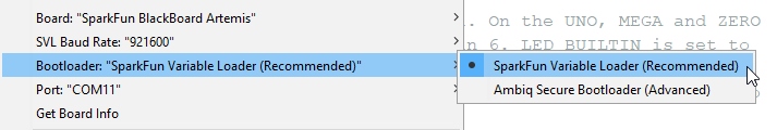
The Artemis modules on these boards come preloaded with two bootloaders. The SparkFun Variable Bootloader (SVL) will allow you reliably and conveniently load new code at data rates up to 921600bps. In addition to the SVL, we also enable the Ambiq factory bootloader for secure boot applications. Almost all users should use the SparkFun Variable Bootloader and forget about the Ambiq factory bootloader. For more information checkout the programming section of the Designing with the Artemis Module tutorial. Don't worry - you cannot damage or brick your Artemis using the incorrect bootloader.
Don't select Ambiq Secure Bootloader unless you know what you're doing
Note: For users who are using the Ambiq Secure Bootloader to upload Arduino sketches.... beware - there seems to be some sort of issue when uploading with the Serial Monitor left open. Even though the upload completes successfully the program does not execute.
Status LED: Blink
The status LED is great for troubleshooting and debugging code. For all of our boards with an Artemis module, the status LED can be accessed in the Mbed-CLI with the variable LED1. However, we have already linked the LED_BUILTIN variable to the Blink example built into the Arduino IDE.
Blink
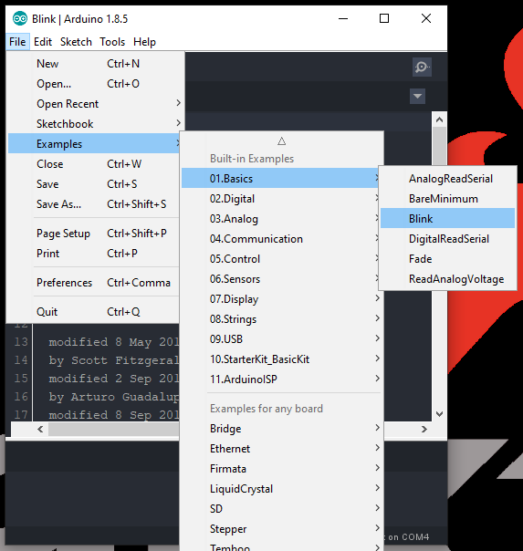
With full Arduino support, users will be able to implement the built-in examples of the Arduino IDE on the Artemis DK. To begin, let's start with the most basic example: Blink. From the drop down file menu, pull up the script:
Screen shot of the built-in Blink example in the Arduino IDE.
Note: Users who need the compiled binary code in order to program the Artemis DK, save this example somewhere that is easily accessible; the desktop is a good option. (*Remember to use Save As, so that you retain the original example within the Arduino IDE.)
Blink example being saved to the Desktop.
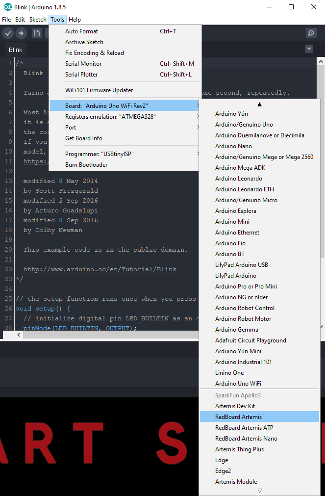
Next, you will want to select the appropriate board from the tools drop down menu: Tools > Board: > Select a Board
Selecting an Artemis board definition in the Arduino IDE.
The last step is to program your board. Use the programming method associated with your board.
Operation
This example is very fundamental and should result in the LED blinking on and then off, with a period of a second. Follow the steps for programming the associated board to see the code in action.
A demonstration of the STAT LED blinking.
Serial Port: Hello World and Enabling Peripherals
In this example, we will create a code that outputs Hello World to the serial monitor, through the USB connection of the associated board. Unfortunately, there isn't an example built into the Arduino IDE, so users will need to copy and past the code below.
language:c
// the setup routine runs once when you press reset:
void setup() {
  // initialize serial communication at 9600 bits per second:
  Serial.begin(9600);
}

// the loop routine runs over and over again forever:
void loop() {
  // print out "Hello World"
  Serial.println("Hello World");
  delay(500);
}
This example outputs Hello World to the serial monitor, through the USB connection of the associated board. Follow the steps for programming the associated board to see the code in action.
Once the board is programmed, open the serial monitor on the Arduino IDE; make sure to set the baud rate to 9600 baud. Hello World should be printed out continuously.
Hello World print out in the Arduino IDE Serial Monitor.
Configuring Peripheral Serial Ports/Pins
In order for users to understand how to adapt their code to configure the peripheral UART ports and pins, we have provided a built-in example for the Apollo3 core. From the file drop-down menu: File > Examples > Apollo3 > Serial.
Built-in Serial example for the Apollo3 core.
ADC: AnalogRead
The ADC pins are useful for measuring analog voltage inputs. To get started, we have provided a built-in example for the Apollo3 core. From the file drop-down menu: File > Examples > Apollo3 > AnalogRead.
Built-in AnalogRead example for the Apollo3 core.
Wiring
Users should be familiar with the ADC example in the SIK. Please, remember that some boards are rated at 3.3V; and therefore, the potentiometer should be tied to 3.3V on the high side.
Operation: Serial Monitor
This example outputs ADC values to the serial monitor, through the USB connection of the associated board. Follow the steps for programming the associated board to see the code in action.
Once the board is programmed, open the serial monitor on the Arduino IDE; make sure to set the baud rate to 115200 baud. A 14-bit value should be printed out based on the associated ADC input voltage.
A print out of the voltage measured by the ADC pin, on the Arduino IDE Serial Monitor.
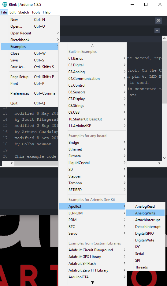
PWM: AnalogWrite
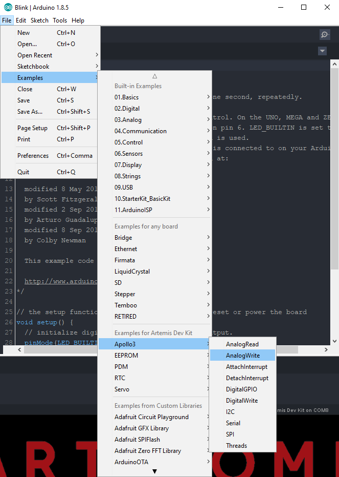
The PWM pins are useful for controlling servos or emulating an analog voltage functionality. To get started, we have provided a built-in example for the Apollo3 core. From the file drop-down menu: File > Examples > Apollo3 > AnalogWrite.
Built-in AnalogWrite example for the Apollo3 core. (Click to enlarge)
Operation
This example is very fundamental and should result in the LED dimming/fading on and off. Follow the steps for programming the associated board to see the code in action.
The brightness of the LED should cycle, fading in and out. (Click to enlarge)
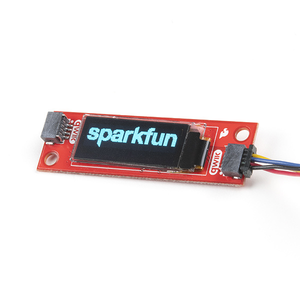
I2C: Qwiic OLED Display
The I2C pins are useful connecting to peripheral devices. In this example, let's use the Qwiic OLED Display and the example code from the online tutorial.
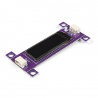
The SparkFun Qwiic OLED Display can display up to three lines of text and features 128x32 pixels in a small 0.91” (diagonal…
Retired
The hookup guide direct users through the installation of the associated Arduino libraries. Once the library is installed, follow the instructions from the online tutorial to get the example up and running.
Note: In the Apollo3 Arduin core, the Wire library (for the I2C communication) is configured to use the dedicated I2C pins attached to a board's Qwiic connector, by default.
This example display various patterns across the display. Follow the steps for programming the associated board to see the code in action.
The Zio OLED display running with the example code from their online tutorial.
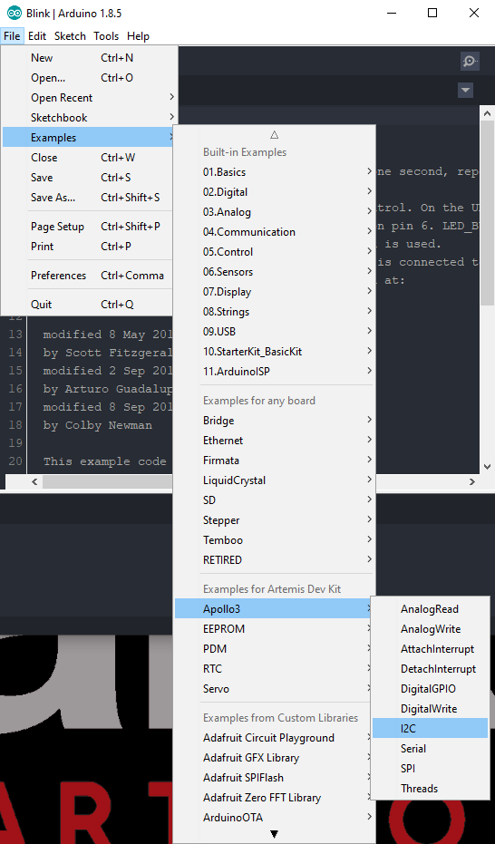
Configuring Peripheral I2C Ports/Pins
In order for users to understand how to adapt their code to configure the peripheral I2C ports, we have provided the following example for the Apollo3 core: File > Examples > Apollo3 > I2C.
Built-in I2C example for the Apollo3 core. (Click to enlarge)
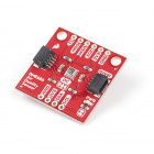
SPI: BME680 Environmental Sensor
The SPI pins are useful connecting to peripheral devices, with high-speed communication. In this example, let's use the SparkFun Environmental Sensor Breakout - BME680 and the SPIDemo example from the library provided for the product. Additional, materials like hookup wire and soldering equipment will be required.
Users will need to follow the hookup guide to install the associated Arduino libraries. Once the library is installed, select the SPIDemo example from the File > Examples > BME680 > SPIDemo menu. Refer to the board's hookup guide to verify the pins utilized for the SPI library; the example code may need to be adapted.
Wiring
Users will need to follow the hookup guide to connect the sensor properly. Soldering the appropriate SPI connections using some hookup wire.
Operation: Serial Monitor
This example outputs sensor values to the serial monitor, through the USB connection of the associated board. Follow the steps for programming the associated board to see the code in action.
Once the board is programmed, open the serial monitor on the Arduino IDE; make sure to set the baud rate to 9600 baud. The environmental sensor readings should be be displayed on the Serial Monitor.
Configuring Peripheral SPI Ports/Pins
In order for users to understand how to adapt their code to configure the peripheral SPI ports, we have provided the following example for the Apollo3 core: File > Examples > Apollo3 > SPI.
Built-in SPI example for the Apollo3 core. (Click to enlarge)
Bluetooth: LED
Install BLE Library
For users interested in the BLE functionality of the Apollo3 and Artemis boards, we have provided full support to the Arduino BLE library. Additional details about the library can be referenced from the documentation provided by Arduino.
Users who haven't already done so, will need to install the Arduino BLE library to continue with this example; please use the guide below, to get started with installing the Arduino BLE library:
How do I install a custom Arduino library? It's easy! This tutorial will go over how to install an Arduino library using the Arduino Library Manager. For libraries not linked with the Arduino IDE, we will also go over manually installing an Arduino library.
Peripheral LED Example
Note: Users will need to download the NRF Connect app onto their phone. We highly recommend utilizing an Android phone as we have had difficulties with device connections in the app for Apple phones.
As in the prior examples, these steps will follow a similar procedure.
From the drop down file menu, open the LED sketch: File > Examples > ArduinoBLE > Peripheral > LED.
Save the sketch (File > Save As...) using the file drop down menu.
Select the then, export the compiled binary code (Sketch > Export compiled Binary) using the sketch drop down menu.
Drag and drop (or copy) the binary .bin file into the ARTEMIS mass storage drive. The storage drive will automatically eject once the programming is complete.
To verify that the board is working and that the programming was successful, open a terminal emulator, such as TeraTerm or the Serial Monitor in the Arduino IDE. Connect to the serial port for the Artemis DK; don't forget to set the baud rate to 9600 bps.
Click the reset button to begin the program. Users should see a BLE LED Peripheral message in the terminal emulator.
Follow the steps and video below to control the STAT LED on the Artemis DK.
Unlock the phone and enable the Bluetooth.
Open the NRF app.
Click on the Scan button on the upper right corner.
In the results, locate the device labeled LED. Click on the CONNECT button to the right of the device name.
In the terminal emulator, users should see a Connected to central: message followed by the mac address of the phone.
Once connected, locate the Unknown Service. It will have the following service UUID: 19B10000-E8F2-537E-4F6C-D104768A1214.
Click on the service. Then, locate and click on the upload button (up arrow).
A dialog box will open. We want to write a value, so locate the New Value text field, under the Write value drop-down menu option. Based on the control inputs to the LED, an LED on or LED off message will appear in the terminal emulator.
Enter 01 to turn the LED on. Then click the SEND button.
Enter 00 to turn the LED off. Then click the SEND button.
Utilizing the example with the NRF phone app.
Serial output of the LED Bluetooth example. (Click to enlarge)
What About Interrupts?
Interrupts allow users to interrupt the code running in the main loop of their code and execute another set of instructions (with an interrupt handler or interrupt service routine) before returning back to the main loop.
What is an interrupt? In a nutshell, there is a method by which a processor can execute its normal program while continuously monitoring for some kind of event, or interrupt. There are two types of interrupts: hardware and software interrupts. For the purposes of this tutorial, we will focus on hardware interrupts.
Check out these Arduino pages for more information on interrupts:
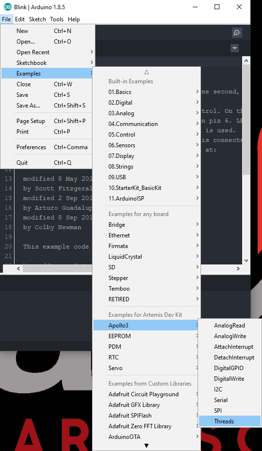
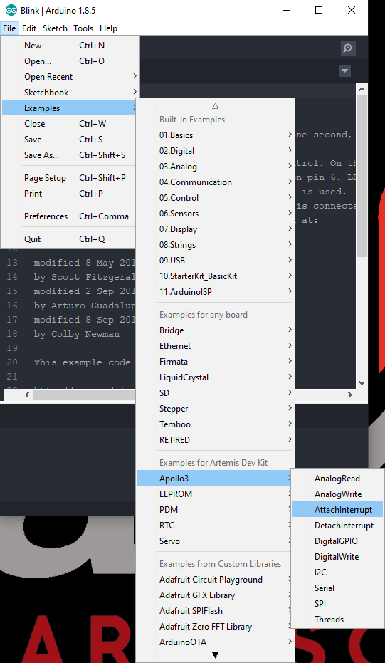
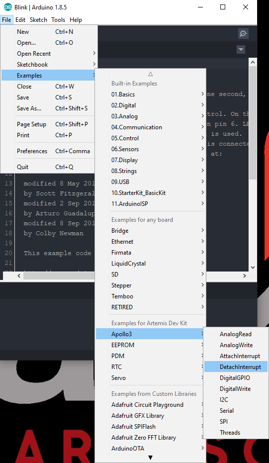
With the incorporation of Mbed™ OS into the Apollo3 Arduino core, to support the Bluetooth functionality, it now functions as a RTOS. This increases the complexity of the code implementation. In order to help users understand how to adapt their code to utilize interrupts, we have provided the following examples for the Apollo3 core: File > Examples > Apollo3 > Pick Example
Below, we have also included some additional troubleshooting tips for issues that you may come across with the Artemis Development Kit.
One of our employees compiled a great list of troubleshooting tips based on the most common customer issues. This is the perfect place to start.
For any Arduino IDE specific issues, we recommend starting with their troubleshooting guide.
If neither of the troubleshooting guides above were able to help, here are some tips you might have missed. (Most of this material is summarized from the tutorial.):
Are You Using a Recommended Computer OS?
This board is not compatible with the Arduino Web IDE. We do NOT recommend using a Chromebook, Netbook, tablet, phone, or the Arduino Web IDE in general. If you are here, try a RECOMMENDED operating system.
My Board Isn't Working:
Every Artemis board gets tested before getting packaged up. That being said, let's try a basic test to see if just the board is working. Disconnect everything that you have attached to the board; we just want to test the board.
Inspect the board:
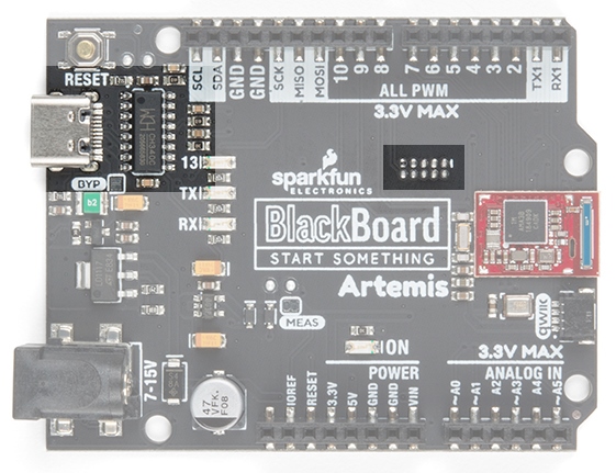
Check the board to make sure everything looks about right. Use the pictures on the product page to verify component placement or alignment, and bad solder joints, or damage.
Power and check the status LEDs:
Using a known good USB-C cable, plug your board in to the computer. Do any of the status LEDs turn on?
New boards, out of the bag, usually come programmed with a test sketch. Often it is a sketch that blinks that status LED at a rate of approximately 2 blinks per second.
Test a Blink sketch:
Try to program the blink sketch. Why blink? It is simple, known to work (from the example files), and you have an indicator LED.
Double check that you have the proper Board selected prior to uploading or exporting the compiled binary.
For boards that are already running the blink example, I recommend changing the timing parameters to check for a change in the board's response.
Verify that you see the status LED blinking properly. If you are having trouble compiling or exporting the binary file for the Artemis DK, try using this pre-compiled binary file.
Driver Installation:
The CH340 serial-to-UART chip may require the latest driver to operate properly. For the associated boards, make sure that the driver is up to date. For instructions for updating your driver, please refer to the CH340 driver installation tutorial.
I Don't See My Board on a Serial/COM Port:
If you don't see your board as an available COM port on the Arduino IDE:
Try to re-open the Arduino IDE.
Check the Device Manager to verify that your computer recognizes the board.
The issue might be related to your USB cable. Check that you are using a USB cable capable of data transfers. Some cables only have the power pins connected for charging. A good way to test this is to plug in a device to your USB cable (like a phone). If it doesn't show up as a device or drive, then try a new USB-C cable.
This rarely happens, but it is easy to check. If you are using a USB 3.0 port (you will see a blue "tongue" in the USB jack or bad USB port, try a different USB port. You can also try to test the board on a different computer to double check for a hardware incompatibility (usually with expansion boards).
Errors Uploading to the Board:
There are two types of issues that you will usually see in the console of the Arduino IDE, compile errors or upload errors. The easiest way to see where to start is by clicking the Verify button (check mark); the Arduino IDE will try to compile your code. A failure here is a compile error.
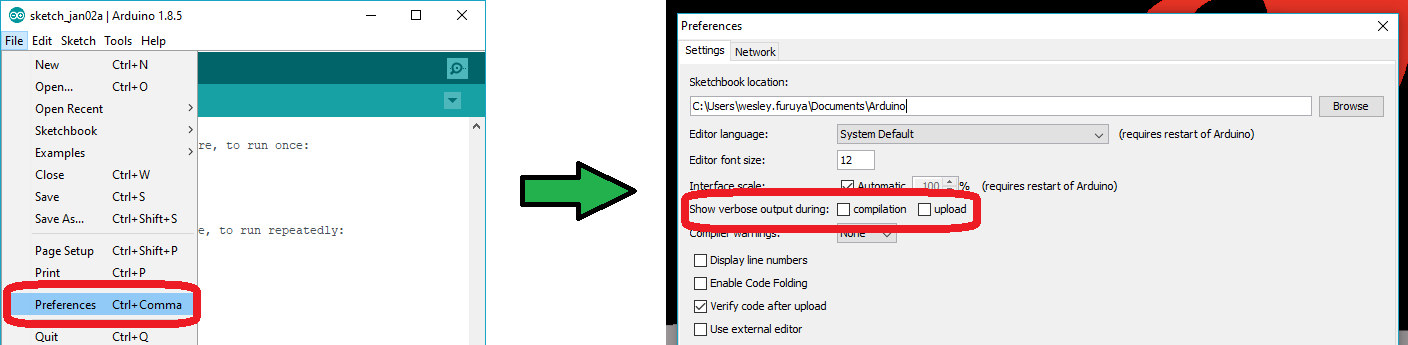
It takes a some experience, but if you enable the verbose output from the Arduino IDE preferences, it may give you more clues to where the issue is.
Screen shots of how to enable verbose output. Click to enlarge.
Compile Errors:
With compile errors, there are several things that could be causing issues. However, 99% of the time, it is user error. Usually something wrong with your code or the library you are using. Once in a while you will have a file structure issue if you manually added a file/folder in any of the Arduino folders (still user error).
Upload Errors:
Upload errors get a little more tricky. You will usually just see the Arduino IDE trying to upload to the board multiple times. There are usually several different causes for this, often without specific errors in the console. Here are a few common examples:
Wrong Board Selection:
Double check you board selection options. If you uploaded with the wrong board selection, there is a small chance that you may have overwritten the bootloader on the board or damaged the microcontroller.
Missing Bootloader:
If your board has the bootloader flashed, pin 13 will flash several times on power up.
Serial Port Interference:
If a device is communicating to the microcontroller over digital pins 0 and 1, while you are trying to upload code.
Bad USB cable or port (see Serial Port section above).
Additional Tips:
If an input pin is read and that is floating (with nothing connected to it), you may see random data/states. In practice, it is useful to tie an input pin to a known state with a pull-up resistor (to VCC), or a pull-down resistor (to GND).
There is a maximum amount of current an I/O pin can source (provide positive current) or sink (provide negative current). You can usually power small sections of LED strips or small motors, but will run into issue with high power devices.
The pins on your board may use 3.3V logic and aren't directly compatible with 5V devices.
Need more help?
If you need technical assistance or information, head on over to the SparkFun Technical Assistance page for some initial troubleshooting.
If you don't find what you need there, the SparkFun Forums are a great place to find and ask for help. If this is your first visit, you'll need to create a Forum Account to search product forums and post questions.
How do I install a custom Arduino library? It's easy! This tutorial will go over how to install an Arduino library using the Arduino Library Manager. For libraries not linked with the Arduino IDE, we will also go over manually installing an Arduino library.
How do I install a custom Arduino board/core? It's easy! This tutorial will go over how to install an Arduino board definition using the Arduino Board Manager. We will also go over manually installing third-party cores, such as the board definitions required for many of the SparkFun development boards.
Arduino Comparison Guide Uno or Pro Mini? Bluetooth or wireless? When it comes to Arduinos, there are a lot of choices. We've compiled every Arduino development…
Handling PCB jumper pads and traces is an essential skill. Learn how to cut a PCB trace, add a solder jumper between pads to reroute connections, and repair a trace with the green wire method if a trace is damaged.
Get our powerful Artemis based boards (Artemis Nano, BlackBoard Artemis, and BlackBoard Artemis ATP) blinking in less than 5 minutes using the SparkFun Artemis Arduino Core!
What is an interrupt? In a nutshell, there is a method by which a processor can execute its normal program while continuously monitoring for some kind of event, or interrupt. There are two types of interrupts: hardware and software interrupts. For the purposes of this tutorial, we will focus on hardware interrupts.
We will demonstrate how to get started with your SparkFun Edge Board by setting up the toolchain on your computer, examining an example program, and using the serial uploader tool to flash the chip.
Get our powerful Artemis based boards (Artemis Nano, BlackBoard Artemis, and BlackBoard Artemis ATP) blinking in less than 5 minutes using the SparkFun Artemis Arduino Core!
With the latest Artemis DK, board, we now offer full Bluetooth support within the Arduino IDE and development with Mbed™ OS. While we have worked tirelessly to get the Artemis module supported in the next Mbed™ OS release, the next release isn't slated until after the Artemis DK becomes available to the public. Therefore, this post will provide users with a jump start for developing with Mbed™ Studio, prior to the next release (in a beta of sorts), by utilizing our fork of Mbed™ OS.
Running low-power machine learning examples on the SparkFun Edge can now be done using the familiar Arduino IDE. In this follow-up to the initial Edge tutorial, we'll look at how to get three examples up and running without the need to learn an entirely new SDK.