Arduino Wireless Communication via the Electric Imp
 jimblom
Hardware Setup
If you're using the Imp Shield, setup is as simple as soldering on some headers, plugging in the shield, and plugging the Imps in.
But if you're using a Breakout or any other form of Impee, there is a bit of hookup to be done. Here is the circuit we'll be using:
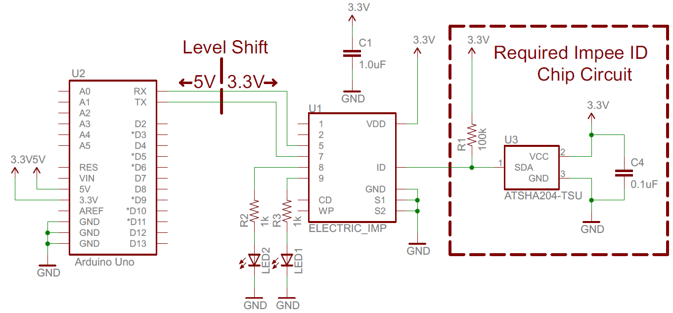
There is some wiggle room with which pins you can use. On the Imp you could use different pins to control the LEDs (or skip the LEDs entirely), or even use one of the other two UARTs (UART12 or UART1289) for communication. On the Arduino, you can use different pins for the SoftwareSerial port (double-check to make sure they'll work with the library though!).
A few things to keep in mind: the Imp is not a 5V tolerant device, so you'll need to shift down any signals above 3.3V. We recommend bi-directional level shifters to accomplish that task (that same circuit is already on the shield).
The Imp can be a power-hungry little devil -- pulling up to 400mA. We've been powering each of the Arduinos/Imp combos off purely USB, and it's worked just fine. Just make sure to keep the power requirements in mind!
We'd really encourage you to branch out on this design. The Imp's got at least 2 more pins for you to make use of. There's an I2C port available on pins 1 and 2, as well as DACs, ADCs, PWM pins...you name it. And, of course, there's tons of room left on the Arduino. Add some sensors, LCDs, LEDs...whatever your project needs!