ZX Distance and Gesture Sensor SMD Hookup Guide
Contributors:
 Shawn Hymel,
  LightningHawk
Shawn Hymel, LightningHawk 
Hardware Hookup
Add Headers
Solder a row of male headers to the nine headers holes on the board.
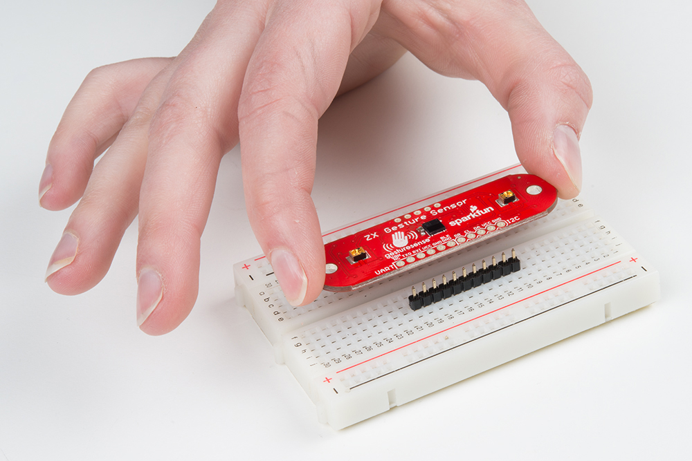
To keep the board from tilting while soldering, place the unused break away headers sideways under the board.
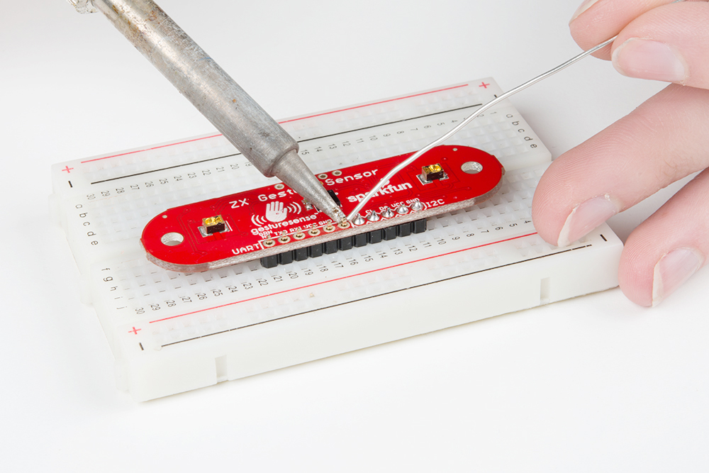
Heads up! Do not solder headers to the row of holes at the top of the board. Those are for programming the PIC microcontroller.
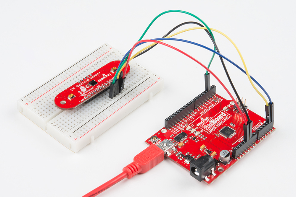
Connect the Breakout Board
For the Arduino examples, we will be using I2C. Connect the breakout board to the following RedBoard pins:
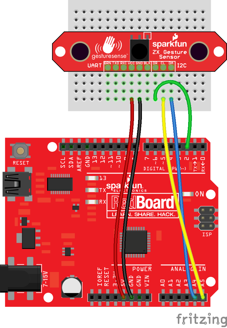
| ZX Sensor | RedBoard |
|---|---|
| VCC | 5V |
| GND | GND |
| DR | 2 |
| CL | A5 |
| DA | A4 |
Note that we connect the DR pin, but we will only use it in the Arduino: Gesture Example. DR stands for "Data Ready," which is active high whenever data is ready to be read from the ZX Sensor. We can attach this to an Arduino interrupt so we don't have to continuously poll the sensor.