Wireless Joystick Hookup Guide
 Alex the Giant
Arduino Examples
Example 1: Remote Tank Steering Motor Controller
For our first example, let's try controlling a robot using tank steering. To use tank steering, you'll need to solder in both joysticks. This examples uses the following parts.
To connect everything, start by soldering the "+" pin of the male deans connector to the motor driver pin that says "MAX 11V" as well as to the 5V pin on the XBee Explorer. Connect the "-" pin of the male deans connector to "GND" on both the motor driver, and XBee Explorer. Next we'll connect the "DOUT" pin of the explorer to the "RX" pin of the motor driver. Solder the motors to the B1/B2 and A1/A2, but be sure the solder the second motor opposite of the first, so that they'll both be spinning in the same direction. The wheels attach to the motors with a friction fit, so carefully push those onto the motor's D-shaft. Finally, attach the XBees to the Wireless Joystick, as well as the to the XBee Explorer.
Adding the Code to the Wireless Joystick
Now that we have everything wired up and soldered together, let's put some code on the Wireless Joystick! To use this example, copy the code below to the Arduino IDE. Make sure you select the SparkFun SAMD21 Dev Breakout as your board.
language:c
/* Wireless Joystick Tank Steering Robot Example
 * by: Alex Wende
 * SparkFun Electronics
 * date: 9/28/16
 *
 * license: Creative Commons Attribution-ShareAlike 4.0 (CC BY-SA 4.0)
 * Do whatever you'd like with this code, use it for any purpose.
 * Please attribute and keep this license.
 *
 * This is example code for the Wireless Joystick to control a robot
 * using XBee. Plug the first Xbee into the Wireless Joystick board,
 * and connect the second to the SparkFun Serial Motor Driver.
 *
 * Moving the left and right joystick up and down will change the
 * speed and direction of motor 0 and motor 1. The left trigger will
 * reduce the maximum speed by 5%, while the right trigger button
 * will increase the maximum speed by 5%.
 *
 * Connections to the motor driver is as follows:
 * XBee - Motor Driver
 *   5V - VCC
 *  GND - GND
 * DOUT - RX
 *
 * Power the motor driver with no higher than 11V!
 */

#define L_TRIG 6        // Pin used for left trigger
#define R_TRIG 3        // Pin used for right trigger
#define L_JOYSTICK A3   // Pin used for left joystick
#define R_JOYSTICK A0   // Pin used for right joystick

int8_t speedLevel = 20; //Maximum speed (%) = speedLevel * 5 (units are percent)

void setup() {
  Serial1.begin(9600); // Start serial communication with XBee at 9600 baud
  delay(10);

  Serial1.print("W7001\r\n"); // Set the bit in enable register 0x70 to 0x01

  pinMode(L_TRIG,INPUT_PULLUP); // Enable pullup resistor for left trigger
  pinMode(R_TRIG,INPUT_PULLUP); // Enable pullup resistor for right trigger
}

void loop() {
  int16_t leftStick, rightStick;    // We'll store the the analog joystick values here
  char buf0[10],buf1[10]; // character buffers used to set motor speeds

  // Reduce top speed
  if(digitalRead(L_TRIG) == 0)
  {
    speedLevel -= 2;
    if(speedLevel < 2) speedLevel = 2;
    while(digitalRead(L_TRIG) == 0)
    {
      delay(2);
    }
  }
  // Increase top speed
  if(digitalRead(R_TRIG) == 0)
  {
    speedLevel += 2;
    if(speedLevel > 20) speedLevel = 20;
    while(digitalRead(R_TRIG) == 0)
    {
      delay(2);
    }
  }

  // Read joysticks
  // Convert analog value range to motor speeds (in %)
  leftStick = (5-(analogRead(L_JOYSTICK)/93))*speedLevel;
  rightStick = (5-(analogRead(R_JOYSTICK)/93))*speedLevel;

  // Build motor 0 buffer
  if(leftStick > 0)
  {
    sprintf(buf0,"M0F%d\r\n",leftStick);
  }
  else
  {
    sprintf(buf0,"M0R%d\r\n",abs(leftStick));
  }

  // Build motor 1 buffer
  if(rightStick > 0)
  {
    sprintf(buf1,"M1F%d\r\n",rightStick);
  }
  else
  {
    sprintf(buf1,"M1R%d\r\n",abs(rightStick));
  }

  // Send motor speeds
  delay(5);
  Serial1.print(buf0);
  delay(5);
  Serial1.print(buf1);
}
Plug in the battery to power the motor driver and receiving XBee and turn on the Wireless Joystick. Moving the left stick should move the left motor, and the right stick should move the right motor. If your left stick is controlling the right motor (or visa versa), swap the pin values for the L_JOYSTICK and R_JOYSTICK at the top of the sketch.
You can slow down the speed of the motors by pressing the left trigger button, and speed up the motor by pressing the right trigger button.
Example 2: USB Game Controller
In order to program a microcontroller from a computer, many microcontrollers like the ATMega328, require another IC to bridge USB to the microcontroller's UART. Other microcontrollers, like the SAMD21 used on the Wireless Joystick, come with native USB, which means there isn't any need for the bridge IC. Having native USB allows us to program the microcontroller and imitate USB devices like keyboards, mice, and gaming joysticks.
In this example, we'll program the Wireless Joystick to help us play a classic game, Asteroids. This example can use either the dual joystick or the single joystick configuration. Let's first upload the code below to our board by copying and pasting it into the Arduino IDE. Make sure you select the SparkFun SAMD21 Dev Breakout as your board. After the code has finished transferring to board, go back to the webpage that has the game on it. Click start and try it out!
language:c
/* Not So Wireless Wireless Joystick USB Example
 * by: Alex Wende
 * SparkFun Electronics
 * date: 9/28/16
 *
 * license: Creative Commons Attribution-ShareAlike 4.0 (CC BY-SA 4.0)
 * Do whatever you'd like with this code, use it for any purpose.
 * Please attribute and keep this license.
 *
 * This example sends ASCII arrow key characters over USB when the left
 * joystick is moved or a space character when right trigger button is pressed.
 */

#include "Keyboard.h"

#define H_JOYSTICK    A2
#define V_JOYSTICK    A3
#define R_TRIGGER     3

void setup() {
  pinMode(R_TRIGGER, INPUT_PULLUP);
  Keyboard.begin();
}

void loop() {
  uint16_t hStick = analogRead(H_JOYSTICK);
  uint16_t vStick = analogRead(V_JOYSTICK);

  if(hStick > 766) Keyboard.press(KEY_LEFT_ARROW);
  else if(hStick < 255) Keyboard.press(KEY_RIGHT_ARROW);
  else{
    Keyboard.release(KEY_RIGHT_ARROW);
    Keyboard.release(KEY_LEFT_ARROW);
  }

  if(vStick > 766) Keyboard.press(KEY_UP_ARROW);
  else{
    Keyboard.release(KEY_UP_ARROW);
  }

  if(digitalRead(R_TRIGGER) == LOW){
    Keyboard.press(' ');
  }
  else{
    Keyboard.release(' ');
  }
}
You can find a free version of Asteroids here. The controls are pretty simple, you can use the left joystick to rotate your rocketship left and right as well as to accelerate forward. To destroy the asteroids, you press the right trigger button.
Example 3: LiPo Battery Monitoring
In this example we'll program the Wireless Joystick to print out information about our battery, such as the remaining charge and the current battery voltage. This example also makes use of the programmable LED to indicate when our battery is running low and it's time to recharge. To use this example, copy the code below to the Arduino IDE. Make sure you select the SparkFun SAMD21 Dev Breakout as your board.
language:c
/* Wireless Joystick battery monitoring Example Code
  by: Jim Lindblom and modified by Alex Wende
  SparkFun Electronics
  date: 9/28/16

  license: Creative Commons Attribution-ShareAlike 4.0 (CC BY-SA 4.0)
  Do whatever you'd like with this code, use it for any purpose.
  Please attribute and keep this license.

  This is example code for the MAX17043G chip on the Wireless Joystick.
  The MAX17043G+U is a compact, low-cost 1S LiPo fuel gauge.
  The SAMD21 talks with the MAX17043 over an I2C (two-wire) interface,
  so we'll use the Wire.h library to talk with it.

  It's a silly example. It reads the battery voltage, and its percentage
  full and prints it out over SerialUSB. You probably wouldn't care about
  the battery voltage if you had the Wireless Joystick connected via USB.
  But this code does show you how to configure the MAX17043G, and how to
  read and manipulate the voltage values.
*/
#include <Wire.h>

#define MAX17043_ADDRESS 0x36  // R/W =~ 0x6D/0x6C

// Pin definitions
int alertPin = 7;  // This is the alert interrupt pin, connected to pin 7 on the Wireless Joystick

// Global Variables
float batVoltage;
float batPercentage;
int alertStatus;

void setup()
{
  pinMode(alertPin, INPUT_PULLUP);

  SerialUSB.begin(9600);  // Start hardware SerialUSB
  delay(500);
  SerialUSB.println("Hello World");

  Wire.begin();  // Start I2C
  configMAX17043(32);  // Configure the MAX17043's alert percentage
  qsMAX17043();  // restart fuel-gauge calculations
}

void loop()
{
  batPercentage = percentMAX17043();
  batVoltage = (float) vcellMAX17043() * 1/800;  // vcell reports battery in 1.25mV increments
  alertStatus = digitalRead(alertPin);

  SerialUSB.print(batPercentage, 2);  // Print the battery percentage
  SerialUSB.println(" %");
  SerialUSB.print(batVoltage, 2);  // print battery voltage
  SerialUSB.println(" V");
  SerialUSB.print("Alert Status = ");
  SerialUSB.println(alertStatus, DEC);
  SerialUSB.println();
  delay(1000);
}

/*
vcellMAX17043() returns a 12-bit ADC reading of the battery voltage,
as reported by the MAX17043's VCELL register.
This does not return a voltage value. To convert this to a voltage,
multiply by 5 and divide by 4096.
*/
unsigned int vcellMAX17043()
{
  unsigned int vcell;

  vcell = i2cRead16(0x02);
  vcell = vcell >> 4;  // last 4 bits of vcell are nothing

  return vcell;
}

/*
percentMAX17043() returns a float value of the battery percentage
reported from the SOC register of the MAX17043.
*/
float percentMAX17043()
{
  unsigned int soc;
  float percent;

  soc = i2cRead16(0x04);  // Read SOC register of MAX17043
  percent = (byte) (soc >> 8);  // High byte of SOC is percentage
  percent += ((float)((byte)soc))/256;  // Low byte is 1/256%

  return percent;
}

/*
configMAX17043(byte percent) configures the config register of
the MAX170143, specifically the alert threshold therein. Pass a
value between 1 and 32 to set the alert threshold to a value between
1 and 32%. Any other values will set the threshold to 32%.
*/
void configMAX17043(byte percent)
{
  if ((percent >= 32)||(percent == 0))  // Anything 32 or greater will set to 32%
    i2cWrite16(0x9700, 0x0C);
  else
  {
    byte percentBits = 32 - percent;
    i2cWrite16((0x9700 | percentBits), 0x0C);
  }
}

/*
qsMAX17043() issues a quick-start command to the MAX17043.
A quick start allows the MAX17043 to restart fuel-gauge calculations
in the same manner as initial power-up of the IC. If an application's
power-up sequence is very noisy, such that excess error is introduced
into the IC's first guess of SOC, the Arduino can issue a quick-start
to reduce the error.
*/
void qsMAX17043()
{
  i2cWrite16(0x4000, 0x06);  // Write a 0x4000 to the MODE register
}

/*
i2cRead16(unsigned char address) reads a 16-bit value beginning
at the 8-bit address, and continuing to the next address. A 16-bit
value is returned.
*/
unsigned int i2cRead16(unsigned char address)
{
  int data = 0;

  Wire.beginTransmission(MAX17043_ADDRESS);
  Wire.write(address);
  Wire.endTransmission();

  Wire.requestFrom(MAX17043_ADDRESS, 2);
  while (Wire.available() < 2)
    ;
  data = ((int) Wire.read()) << 8;
  data |= Wire.read();

  return data;
}

/*
i2cWrite16(unsigned int data, unsigned char address) writes 16 bits
of data beginning at an 8-bit address, and continuing to the next.
*/
void i2cWrite16(unsigned int data, unsigned char address)
{
  Wire.beginTransmission(MAX17043_ADDRESS);
  Wire.write(address);
  Wire.write((byte)((data >> 8) & 0x00FF));
  Wire.write((byte)(data & 0x00FF));
  Wire.endTransmission();
}
Example 4: Using the Extra GPIO
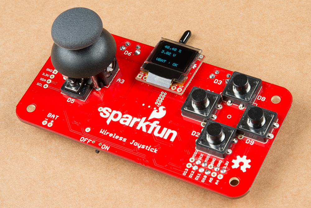
You may have noticed that the SPI, I2C, and other GPIO pins have been broken out. We wanted to breakout the unused pins to allow for any customization that you may want. In this final example, we'll use the OLED screen to display battery information from the MAX17043 fuel gauge.
Before we look at the code, let's wire up the OLED Breakout. You'll need seven wires to connect the OLED Breakout to the Wireless Joystick, their connections are:
Wireless Joystick - OLED Breakout
- 3.3V - 3V3
- GND - GND
- MOSI - SDI
- SCK - SCK
- D10 - CS
- D11 - RST
- D12 - D/C
Where you place the OLED screen is up to you, but I personally like to use foam doubled sided tape to mount the display on the top of the board by the USB connector.
To use the code below, you'll want to download the MicroOLED Arduino library first. To download the libary, click the button below, or grab the latest version from our GitHub repository. For more information on how to use the libary, visit the Micro OLED Breakout Hookup Guide.
After installing the library, copy the code below to the Arduino IDE. Make sure you select the SparkFun SAMD21 Dev Breakout as your board.
language:c
/* GPIO Example For the Wireless Joystick
 * by: Alex Wende
 * SparkFun Electronics
 * date: 9/28/16
 *
 * license: Creative Commons Attribution-ShareAlike 4.0 (CC BY-SA 4.0)
 * Do whatever you'd like with this code, use it for any purpose.
 * Please attribute and keep this license.
 *
 * This example the SparkFun OLED Breakout (LCD-13003) to display
 * the battery's voltage and remaining charge.
 *
 * Connections:
 * Wireless Joystick - OLED
 * 3.3V - 3V3
 *  GND - GND
 * MOSI - SDI
 *  SCK - SCK
 *  D12 - D/C
 *  D11 - RST
 *  D10 - CS
 */

#include <SPI.h>
#include <Wire.h>
#include <SFE_MicroOLED.h>

#define PIN_RESET 11  // Connect RST to pin 9 (req. for SPI and I2C)
#define PIN_DC    12  // Connect DC to pin 8 (required for SPI)
#define PIN_CS    10 // Connect CS to pin 10 (required for SPI)
#define DC_JUMPER 0

#define MAX17043_ADDRESS 0x36

// Pin definitions
int alertPin = 7;  // This is the alert interrupt pin, connected to pin 7 on the Wireless Joystick
int ledPin = 13;   // This is the pin the led is connected to

// Global Variables
float batVoltage;
float batPercentage;
int alertStatus;

MicroOLED oled(PIN_RESET, PIN_DC, PIN_CS);

void setup()
{
  oled.begin();  // Start OLED
  Wire.begin();  // Start I2C

  pinMode(alertPin, INPUT_PULLUP);  // Enable pullup resistor
  pinMode(ledPin, OUTPUT);
  configMAX17043(32);  // Configure the MAX17043's alert percentage
  qsMAX17043();  // restart fuel-gauge calculations

  oled.setFontType(0);  // Set the text to small (10 columns, 6 rows worth of characters)
}

void loop()
{
  batPercentage = percentMAX17043();  // Get battery percentage
  batVoltage = (float) vcellMAX17043() * 1/800;  // vcell reports battery in 1.25mV increments
  alertStatus = digitalRead(alertPin);

  oled.clear(PAGE); // clears the screen
  oled.setCursor(0,0);  // move cursor to top left corner
  oled.print(batPercentage, 2);
  oled.println(" %\n");

  oled.print(batVoltage, 2);
  oled.println(" V\n\n");

  oled.print("VBAT : ");
  if(alertStatus == LOW){
    digitalWrite(ledPin, HIGH);
    oled.print("LOW");
  }
  else{
    digitalWrite(ledPin, LOW);
    oled.print("OK");
  }
  oled.display();
  delay(10);
}

/*
vcellMAX17043() returns a 12-bit ADC reading of the battery voltage,
as reported by the MAX17043's VCELL register.
This does not return a voltage value. To convert this to a voltage,
multiply by 5 and divide by 4096.
*/
unsigned int vcellMAX17043()
{
  unsigned int vcell;

  vcell = i2cRead16(0x02);
  vcell = vcell >> 4;  // last 4 bits of vcell are nothing

  return vcell;
}

/*
percentMAX17043() returns a float value of the battery percentage
reported from the SOC register of the MAX17043.
*/
float percentMAX17043()
{
  unsigned int soc;
  float percent;

  soc = i2cRead16(0x04);  // Read SOC register of MAX17043
  percent = (byte) (soc >> 8);  // High byte of SOC is percentage
  percent += ((float)((byte)soc))/256;  // Low byte is 1/256%

  return percent;
}

/*
configMAX17043(byte percent) configures the config register of
the MAX170143, specifically the alert threshold therein. Pass a
value between 1 and 32 to set the alert threshold to a value between
1 and 32%. Any other values will set the threshold to 32%.
*/
void configMAX17043(byte percent)
{
  if ((percent >= 32)||(percent == 0))  // Anything 32 or greater will set to 32%
    i2cWrite16(0x9700, 0x0C);
  else
  {
    byte percentBits = 32 - percent;
    i2cWrite16((0x9700 | percentBits), 0x0C);
  }
}

/*
qsMAX17043() issues a quick-start command to the MAX17043.
A quick start allows the MAX17043 to restart fuel-gauge calculations
in the same manner as initial power-up of the IC. If an application's
power-up sequence is very noisy, such that excess error is introduced
into the IC's first guess of SOC, the Arduino can issue a quick-start
to reduce the error.
*/
void qsMAX17043()
{
  i2cWrite16(0x4000, 0x06);  // Write a 0x4000 to the MODE register
}

/*
i2cRead16(unsigned char address) reads a 16-bit value beginning
at the 8-bit address, and continuing to the next address. A 16-bit
value is returned.
*/
unsigned int i2cRead16(unsigned char address)
{
  int data = 0;

  Wire.beginTransmission(MAX17043_ADDRESS);
  Wire.write(address);
  Wire.endTransmission();

  Wire.requestFrom(MAX17043_ADDRESS, 2);
  while (Wire.available() < 2)
    ;
  data = ((int) Wire.read()) << 8;
  data |= Wire.read();

  return data;
}

/*
i2cWrite16(unsigned int data, unsigned char address) writes 16 bits
of data beginning at an 8-bit address, and continuing to the next.
*/
void i2cWrite16(unsigned int data, unsigned char address)
{
  Wire.beginTransmission(MAX17043_ADDRESS);
  Wire.write(address);
  Wire.write((byte)((data >> 8) & 0x00FF));
  Wire.write((byte)(data & 0x00FF));
  Wire.endTransmission();
}